This thread has been locked.

If you have a related question, please click the "Ask a related question" button in the top right corner. The newly created question will be automatically linked to this question.

Thermal resistance Rθja of DDA Package 8-Pin SO PowerPAD

Part Number: LP38852

Tool/software:

Hi all,

I would like to know the thermal resistance Rθja of LP38852MRX-ADJ/NOPB.
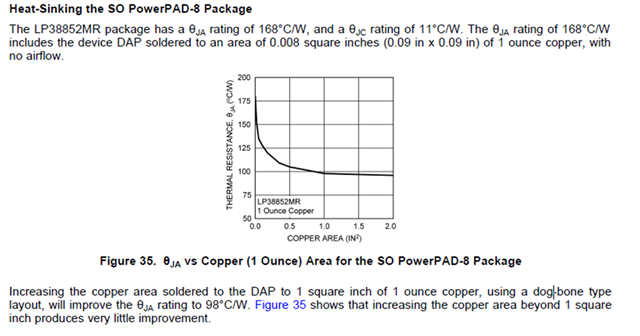
LP38852MRX-ADJ/NOPB is DDA Package 8-Pin SO PowerPAD.

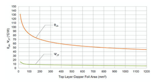
In the past data sheet, there was a graph that changes with distance from Copper area.

In the latest data sheet, Rθja is 48.4, but I think it varies as shown in the graph above.

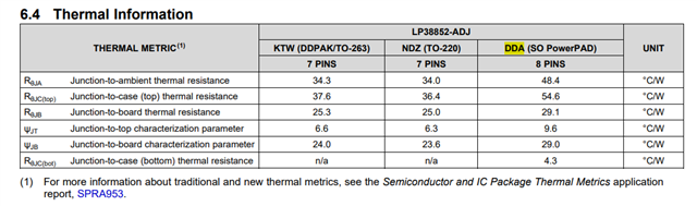
Is there a graph that shows how much it varies from 48.4?

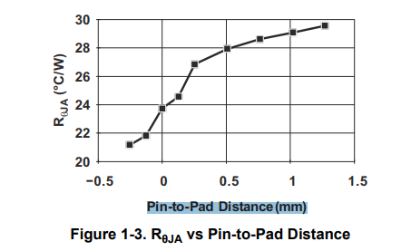
In the application note below, it was mentioned that it varies with Pin-to-Pad Distance (mm), but I didn't understand what it meant.

Semiconductor and IC Package Thermal Metrics (Rev. D)

Best Regards,

Ryusuke

  • Hello Ryusuke,

    The Rθja of LP38852MRX-ADJ/NOPB in DDA package shown in table 6.4 was calculated based on a Jedec 2s2p board described in document JESD51-7 with thermal via array for exposed pad packages described in document JESD51-5.

    The graph from figure 35 has a different Rθja than the value shown in table 6.4 since the calculation was based on a single side 1oz cu area, which is different from the Jedec 2s2p board.

    We do not have a graph that shows the change in θja vs Copper area for a 2s2p jedec board.

    Regards,

    Daniel

  • Hi Daniel,

    My customer understood that there is no graph.

    I looked up the measurement with JESD51-5 on the following website.

    Thermal Resistance Data: Real-World Data Examples | What is thermal design? | TechWeb

    It seems that θja is always curved because it varies greatly depending on the environment.
    I understand that saturation occurs when the IC drops to some extent, which is the same trend regardless of IC.

    [Question]

    Is 48.4°C/W the maximum value on the curve or the minimum value after saturation?


    We are testing the actual machine. We would like to receive an answer from the manufacturer and use it as a reference for verification.
    We would appreciate it if you could let us know.

    Best Regards,

    Ryusuke

  • Hello Ryusuke,

    The specified Rθja in the datasheet is in steady state. We consider steady state when the device is no longer changing temperature by ±0.5 °C/W after 1 minute.  

    Regards,

    Daniel

  • Hi Daniel,

    What happens when the temperature changes? Does the thermal resistance increase or decrease?

    I think it depends on whether 48.4°C/W is the maximum value or the minimum value.

    Best Regards,

    Ryusuke

  • Hello Ryusuke,

    The internal die temperature depends on the power being dissipated across the pass element of the regulator. For every watt of power, the die temperature will increase about 50°C above the ambient temperature. There are other factors like the heat dissipation capability of the power pad, air flow, etc that can reduce the die temperature. If the power pad is soldered to a pcb with sufficient heat sinking capability, the Rθja can be considered as the maximum value, but if there is no heat sinking capability of the pcb, this may become the minimum value.

    Best regards,

    Daniel