Tool/software:
I used the LM74700QDBVRQ1 integration on my newly designed PCB. However, during my tests, I realized that the ideal diode was not triggered as desired.
When I looked at the design, I saw that I was acting according to the requirements. I don't understand the problem.
The features of my design are as follows;
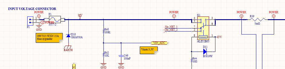
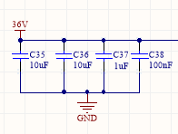
36V input voltage
Ability to transmit current up to 10A to the output
36V Output voltage
I control the opening and closing of the line with a relay via mcu.
I am reading current with a shunt resistor on the line.
I am using SQJ476EP-T1_GE3 ( Vishay Siliconix ) as mosfet.
In my tests there is no voltage difference on Vcap ( inV outV.) = 0,5v
Even at high current there is a voltage drop of 0.5V. and the mosfet body heats up due to the diode.
note: I saw that the connections of the mosfet and ideal diode were correct and trouble-free in the tests I made.
when I connected the output 10 ohms and 5K, I saw that the system continued in the same way without triggering.
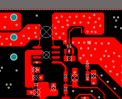
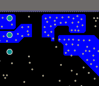
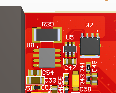
Necessary pictures are attached.
I am waiting for your help and suggestions. Thanks in advance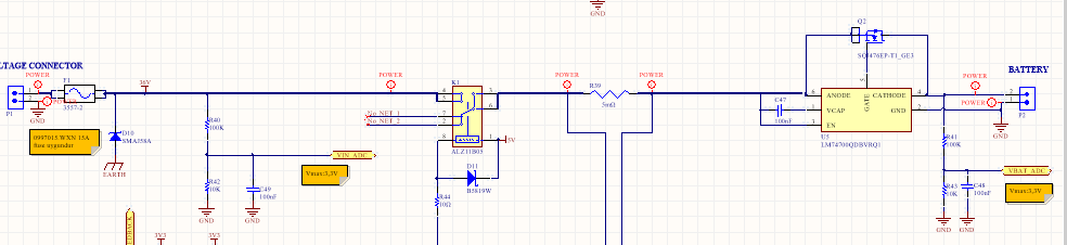
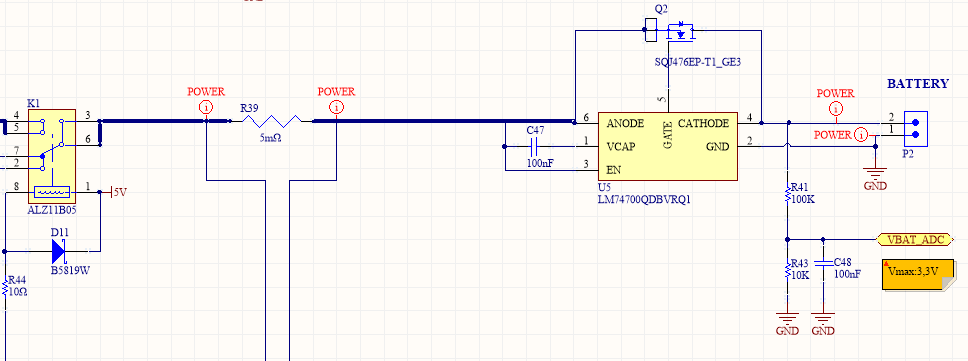
voltage value on Vcap