This thread has been locked.

If you have a related question, please click the "Ask a related question" button in the top right corner. The newly created question will be automatically linked to this question.

LMZ31710: How to set Desired Switching Frequency for a 0.95V output

Part Number: LMZ31710

Tool/software:

Hi

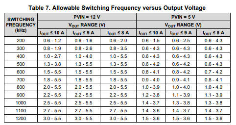
I datasheet it says that "Adjustable switching frequency (200 kHz to 1.2 MHz)"

But again table 2 of the data sheet suggests a defined Fsw for a particular output.
Can I program my Fsw other than this table or I have to follow the table.
Because I want to set 550kHz as my Fsw but the table suggests 250kHz,
even if I go with 250kHz the webench simulation the phase margin is 46. So two questions.

1. can I improve my phase margin by any external circuitry at 250kHz
2. or can I program my Fsw to 550kHz using Rrt resistor.

Regards,
Raju

  • Hi 

    will get back to you on monday

    Thank you

    Savith

  • Hi

    While the table is discreet, should be able to scale things with the switching frequency, so 550kHz would be halfway between the 500kHz and 600kHz settings

    But for 12 to 0.95V , it is not recommended for switching frequency greater than 350kHz.  This would be due to minimum on-time restrictions

    A feedforward capacitor could likely help with phase boost at crossover, but It depends on what the BODE plot looks like, so it's a little hard for me to say.

    But in general if youare on the falling side of the phase with 46 degrees, adding Cout to reduce the loop bandwidth could boost phase on the rising side of Phase with 46 degrees a feed-forward capacitor or reduced Cout could boost phase

    changing the switching frequency to 350kHz might get phase boost.  Or 550kHz if 5V input

    Thank you

    Savith