This thread has been locked.

If you have a related question, please click the "Ask a related question" button in the top right corner. The newly created question will be automatically linked to this question.

BQ25798: After disabling OTG, the situation of enabling OTG immediately occurs

Part Number: BQ25798
Other Parts Discussed in Thread: TPS25751

Tool/software:

Hi teams:

When the power bank (tps25751) is on low battery, we stop supplying power to external devices, i.e. disable the OTG of charger and close the mofset
But after the occurrence of a disable otg, it was immediately enabled, and then disabled otg again... This resulted in the problem of repeatedly switching between disable and enable states, and external devices were also switching between stop charging and charging states
May I ask what caused this? How should I correctly operate when I want to stop supplying power to external devices?

Best Regards!

Iris

  • Hi Iris,

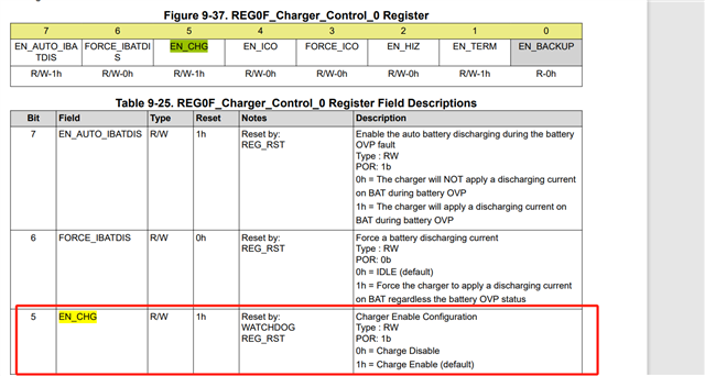
    The charger OTG is disabled when EN_OTG bit is written to 1.  If EN_CHG bit is set 1, the charger immediately starts charging when EN_OTG is written to 0. If there is no input voltage at charger's VBUS pin, the charger auto enters HiZ mode.

    Which mosfet are you closing?

    Regards,

    Jeff

  • Hi Jeff,

    1)Shouldn't the charger OTG be disabled when the EN_OTG bit is written to 0?

    2)After disabling otg, we write EN_CG to 0, but the above phenomenon still occurs

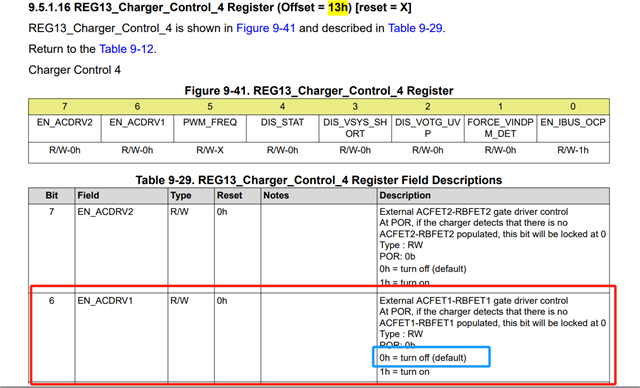
    3)close mosfet:Write Bit6 in the REG13_Charger_Control. 4 Register to 0, and when Enable OTG, write BIT6 to 1,Wrote 0x21 to this register

    4)We are trying to use another method to stop and restore power supply to external devices

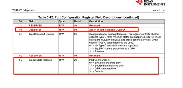
    Stop charging external devices:Write bit1~0 to 3 and bit10 to 1 in the Port Configuration Register (Offset=28h)

    Resume charging external devices:Write bit1~0 to 2 and bit10 to 0 in the Port Configuration Register (Offset=28h)

    When the battery level is less than 20%, it is possible to stop charging external devices, but the role changes from source to sink;
    After the battery level is restored to 20%, it is impossible to resume charging external devices. At this time, the role is still the role. How should charging be restored in this situation?

  • Hi LI,

    Regarding 1, yes.  

    Regarding 2, EN_CHG=0 stops charge current from SYS to BAT but the converter still runs to regulate SYS voltage.  If you want the converter off with input power attached, set EN_HIZ=1.

    Regarding 3, setting EN_ACDRV1 = 0 momentarily turns off (opens) the input MUX FETs but, if valid VAC1 is present, ACDRV1 output immediately turns back on.  To turn off both ACDRV1 and ACDRV2, the host can write DIS_ACDRV bit =1 in REG0x12[7].  

    Regards,

    Jeff

  • Hi Jeff

    1)May I ask if it is necessary to perform both set ENH_IZ=1 and write DIS-ACDRV bit=1 in REG0x12 [7] in order to stop charging the phone?
    If the battery level reaches 20% and the phone needs to be charged, do we need to set ENH_IZ=0 and write DIS-ACDRV bit=0 in REG0x12 [7]?

    2)We are trying to use another method to stop and restore power supply to external devices today.
    Stop charging external devices:Write bit1~0 to 3 and bit10 to 1 in the Port Configuration Register (Offset=28h)
    Resume charging external devices:Write bit1~0 to 2 and bit10 to 0 in the Port Configuration Register (Offset=28h)
    When the battery level is less than 20%, it is possible to stop charging external devices, but the role changes from source to sink;
    After the battery level is restored to 20%, it is impossible to resume charging external devices. At this time, the role is still the role. How should charging be restored in this situation?

    Best Regards!

    Iris

  • Hi Iris,

    Regarding 1, if there is a voltage>3.6V at VACx, then setting DIS_ACDRV=1 removes input power from VBUS and stops charging so no need to set EN_HIZ=1.  

    Regarding 2, that is a TPS25751 question so I will move this post to that team.

    Regards,

    Jeff

  • Hi Iris, 

    Stop charging external devices:Write bit1~0 to 3 and bit10 to 1 in the Port Configuration Register (Offset=28h)
    Resume charging external devices:Write bit1~0 to 2 and bit10 to 0 in the Port Configuration Register (Offset=28h)

    Something to be aware of, when TypeCState Machine is set to Disabled, the CCx pins become Hi-Z and no connection can be made (both as source and sink). This means even if a source-only device (such as wall adapter) won't be able to charge the system. Is this the intended behavior or how should the type-C port behave when operating in the "Stop charging external devices" state? 

    I do not recommend setting Disable PD, this only makes TPS25751 operate as a type-C legacy device that can still either source or sink but just no PD messaging. 

    When the battery level is less than 20%, it is possible to stop charging external devices, but the role changes from source to sink;

    This is possible, two options: 

    1. Set TypeC State Machine to Sink State Machine only (0x0), TPS25751 will always present itself as a sink only device upon connection. 

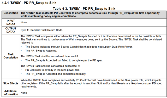
    2. With MCU, send 4CC command 'SWSk' to instruct TPS25751 to send PR_Swap request to port partner to become a sink. This command only works with port partner devices that have DRP capability. 

    Let us know if you have any further questions or concerns! 

    Thanks and Regards,

    Raymond Lin

  • Hi Jeff,

    I write DIS_ACDRV bit =1 in REG0x12[7]. When the battery level is less than 20%, instability occurs, and the charging indicator of the phone is flashing (i.e., there is a stop charging cycle). It only stabilizes when the battery level reaches 15%,The phenomenon of visible attachment videos

    The attached image shows the circuit of our battery charger,When capturing logs, there was also an exception caused phenomenon


    Best Regards!

    Iris

  • . Set TypeC State Machine to Sink State Machine only (0x0), TPS25751 will always present itself as a sink only device upon connection. 

    Hi Raymond,

    thanks for your reply.

    We have tried your suggestion.When the battery level is less than 20%,set TypeC State Machine to Sink State Machine only (0x0);It is indeed possible to stop charging the phone, but there is a problem where the phone is charging the tps25751. Why is this?

    when the battery level recovers to over 20%, we need to restore charging to external devices. We set the TypeC State machine to Source State machine only (0x1)


    Best Regards!

    Iris

  • Hi Iris, 

    We have tried your suggestion.When the battery level is less than 20%,set TypeC State Machine to Sink State Machine only (0x0);It is indeed possible to stop charging the phone, but there is a problem where the phone is charging the tps25751. Why is this?

    When the TypeC State Machine is set to sink only, TPS25751 can only connect as a sink device. Most smartphones these days are DRP (Dual Role Power) capable which means they can output power if a sink-only device is connected. 

    What exactly is the desired behavior when the system is in "Stop charging external devices" state? Should TPS25751 remain as DRP capable but also not draw power from the phone? 

    Thanks and Regards,

    Raymond Lin

  • Hi Raymond Lin

    Should TPS25751 remain as DRP capable but also not draw power from the phone? 

    yes,when the system is in "Stop charging external devices" state, not draw power from the phone

     But we don not set the TypeC State machine to disable (0x3)

    What should we do?

    Best Regards!

    Iris

  • Hi Iris, 

    For the scenario where battery is low and the system (with TPS25751) should not source power (assuming TPS25751 is currently in Source Mode):

    1. Phone is connected and acting as sink (TPS25751 is sourcing to phone)

    2. System battery drains to 20%

    3. MCU writes to TPS25751 Transmit Source Capabilities (reg 0x32) and configures the following field where applicable:

    4. Set Number Valid PDOs [2:0] to 0x1 (only advertise first PDO of 5V)

    5. Set Maximum Current [33:24] in Source PDO 1 from the default (i.e. 3A) to 0x0 (0A)

    6. MCU send 'SSrC' to re-send the updated Source Capabilities to only advertise 5V/0A

    7. Assuming PD negotiation is successful, 5V/0A is now the new contract and VBUS will be at 5V however no current will be drawn by the phone. 

    In a scenario where the TPS25751 system is a sink to a phone acting as a source, MCU can first send SWSr (PR_Request Swap to Source) to instruct TPS25751 to send a PR_Swap request message to the port partner to become the source. 

    When the system battery is back to more than 20% and the port can resume sourcing, MCU can reset the Number Valid PDOs [2:0] and Maximum Current [33:24] back to the 'default' state and send 'SSrC' to TPS25751 to advertise the updated Source Capabilities. 

    Let us know if you have any further questions or concerns!

    Thanks and Regards,

    Raymond Lin

  • Hi  Raymond Lin

    Thank you for your suggestion. This issue has indeed been resolved

    Thanks!

    Best Regards!

    Iris

  • Hi Iris, 

    No problem, closing this e2e. Please open a new e2e thread for additional support!

    Thanks and Regards,

    Raymond Lin