This thread has been locked.

If you have a related question, please click the "Ask a related question" button in the top right corner. The newly created question will be automatically linked to this question.

TPS63061: Inductor polarity

Part Number: TPS63061

Tool/software:

Hello, 


I am starting a design with the chip TPS63061DSC. 

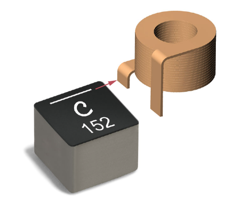
In the datasheet it suggests to place a inductor (L1) reference Coilcraft XFL4020-102. 

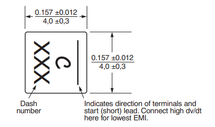
This inductor has polarity, but it is not stated anywhere in the datasheet how should it be placed. 

I am assuming it is like this (named L2 in my design): 
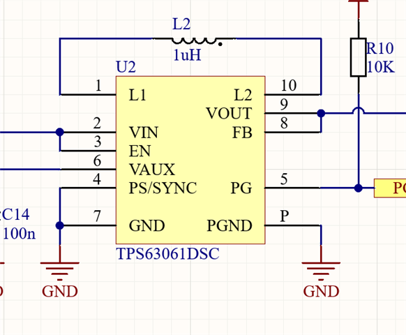
Is this correct?

Thanks

  • Hi Maria,

    Thank you for reaching out. There is no polarity for this inductor, so both ok.

    Regards,

    Mulin

  • Hi Mulin Yuan, 

    Thanks for your answer, but I do not understand it. 

    The inductor acutally comes with polarity: why choosing such an inductor if there is actually no polarity involved? 

    The inductor's datasheet says it could affect EMI. 

    I am not sure it does not matter: I think it does. 

  • Hi Maria,

    White stripe on the Coilcraft inductor marks the short coil lead. Connecting the short lead to SW node of buck or boost converter helps the EMI performance. But for buck-boost converter, both L1 and L2 can be switching node, so there is no big difference from my side. If TPS63061 works in buck mode in most time, you can connect short lead to L1. If more time in boost, you can connect to L2. If buck, boost, buck-boost mode all exist, I think no difference.  For EMI consideration, you can add EMI filter, RC snubber and optimize layout.

    Regards,

    Mulin

  • Hi Mulin. 

    Thank you for your answer! 

    That made things clear. 

    Kind regards :)