This thread has been locked.

If you have a related question, please click the "Ask a related question" button in the top right corner. The newly created question will be automatically linked to this question.

TPS55288: Seeking DCDC IC Recommendations for Project with CC/CV Charging, Sinking (Discharge), and Standby Modes

Part Number: TPS55288
Other Parts Discussed in Thread: LM51772

Tool/software:

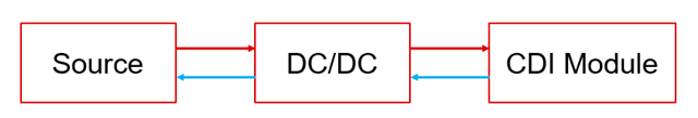
I am working on a project and need some guidance on selecting the right DC-DC IC. Here are the requirements and details of my project:

Requirements:

  1. Charging Phase:

    • CC/CV Operation: The IC should be able to charge the CDI module with a constant current (CC) and have a voltage limit of 12V (CV).
    • Variable Constant Current: The IC should be capable of providing different constant currents (e.g., 1A, 1.1A, 1.2A, 1.3A, etc.) as selected by the user
    • A display board with 10 buttons is used to select the desired current level, and it communicates with an MCU via UART.
  2. Discharge Mode:

    • The DC-DC IC should be able to sink current from the load, which is at 12V.
  3. Standby Mode:

    • In this mode, the IC should provide a constant current of 1A with an output voltage of 6V.

Questions:

  1. IC Selection: Which TI DC-DC IC would be suitable for my project, considering the multiple operating modes and the need for both CC/CV charging and current sinking capabilities?
  2. Configuration and Control: How can I configure and control the selected IC to achieve the desired CC/CV operation, variable current levels, and the different operating modes (charging, discharging, and standby)?
  3. Additional Features: Are there any additional features or considerations I should be aware of when implementing this setup?

Thank you for your help and recommendations!

  • Hi Shah,

    May I know what is the application and product type here?

    What is the sink current capability needed when in Discharge mode?

    TPS55288 can be set as CC or CV mode, but the sink current capability should also be considered as it is not bidirectional device.

    BRs,

    Bryce

  • The product is a Capacitive Deionization (CDI) module, which functions similarly to a capacitor with two electrodes (positive and negative). The module has a capacitance of 300F, and its Equivalent Series Resistance (ESR) varies between 2-8 ohms depending on the water flow.

    Operation Overview:

    1. Charging Phase (Ion Adsorption):
      When water flows through the CDI module, a Constant Current (CC) mode is activated using a power supply as the source. This causes ions in the water to be attracted toward the CDI electrodes.

    2. Discharging Phase (Ion Removal):
      Once the electrodes are fully saturated with ions, the CDI module needs to be discharged. This is done by applying a reverse voltage to the electrodes, allowing the power supply to sink current from the CDI module. This process removes the attracted ions from the electrodes, which are then flushed out as wastewater.

    3. Cycle Repeats:
      After discharging, the CDI module is switched back to the charging mode to begin the process again.

      Discharge Method:

      One common method to discharge the CDI module is by placing a resistor across it, which dissipates the energy. However, this method is relatively slow.

      Lab Testing Results:

      • Charging Time:
        In lab tests, it took approximately 150 seconds to fully charge the CDI module using a DC source set in CC mode.
      • Discharging Time:
        Applying reverse polarity for discharging took about 100 seconds.

    The goal is to design a power supply that can efficiently manage the charging and discharging cycles of the CDI module that should be able to apply reverse voltage and sink current efficiently to discharge the CDI module in a shorter time frame.Instead of simply shorting the CDI module, a controlled discharge using the power supply in current sink mode is needed. This allows to manage the discharge rate and prevent potentially damaging current spikes. 

  • Hi Shah,

    Thanks for the detailed explanation.

    Below is the simplified diagram, with red arrow, the DCDC is working at charging phase, so the current is flowing from source to CDI module. When DCDC is operating at discharging phase, the current will be from CDI module to source(blue), so the source will be charger to higher voltage if source is also battery. Otherwise, there will need some load to dissipate the power.

    TPS55288 can be used at CC or CV mode and is programmable via I2C, but when it is operating at sink mode, the max sink current is about 2A, it means even it is operating at sink mode, the time will be about T=C*V/I=300F*12V/2A=1800seconds.

    What is the source voltage range? And is it ok for the sink current to source?

    BRs,

    Bryce

  • The source is a DC-DC power supply, so it cannot absorb current from the CDI when the CDI is in discharge mode. However, in the lab, we have a DC-DC power supply that can operate in both constant current (CC) and constant voltage (CV) modes. In discharge mode, my colleagues simply reverse the polarity of the supply voltage to the CDI terminals, allowing the CDI to discharge into the power supply within 100 seconds. I'm not sure why the CDI module discharges when reverse voltage is applied, considering it's a power supply and not a battery. If I use a dummy load, like a resistor, to dissipate the energy across the CDI, the discharge time is very long, and finding such a high-power resistor is both difficult and expensive. The resistor must be capable of handling the power dissipation. The maximum power in the resistor would occur at the beginning:

    P_max = I^2 * R = (5A)^2 * 5 ohms = 25 * 5 = 125W.

    This is a significant amount of power and requires a high-power resistor. That's why I need a power supply that can sink current, with a high sinking capability, to discharge the CDI module quickly. 

  • Hi Shah,

    That will be a question, how to dissipate the power when CDI is in discharge mode. Normally for bi-directional applications, the input source would be battery or supercap, so the battery or super-cap can be charged or discharged. 

    You may need to think about where to dissipate the power when in discharge mode. Even with DC/DC, the sink current will also need to charge something or dissipate in some way.

    For the DC/DC selection, as commented before, TPS55288 can be used at CC or CV mode and is programmable via I2C, but when it is operating at sink mode, the max sink current is about 2A, it means even it is operating at sink mode, the time will be about T=C*V/I=300F*12V/2A=1800seconds. If larger sink current and less discharge time is required, you can look at LM51772 which is bi-directional buck-boost converter.

    BRs,

    Bryce