TPS54318: Beat Frequency of 12 kHz at the output

Part Number: TPS54318
Other Parts Discussed in Thread: TPS628503, TPS628303, TPS628513

Tool/software:

Dear TI Forum, 

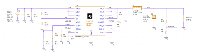
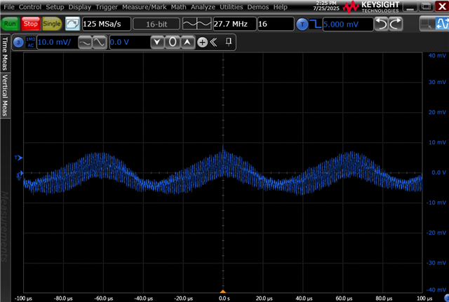
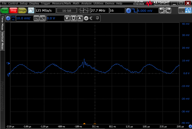
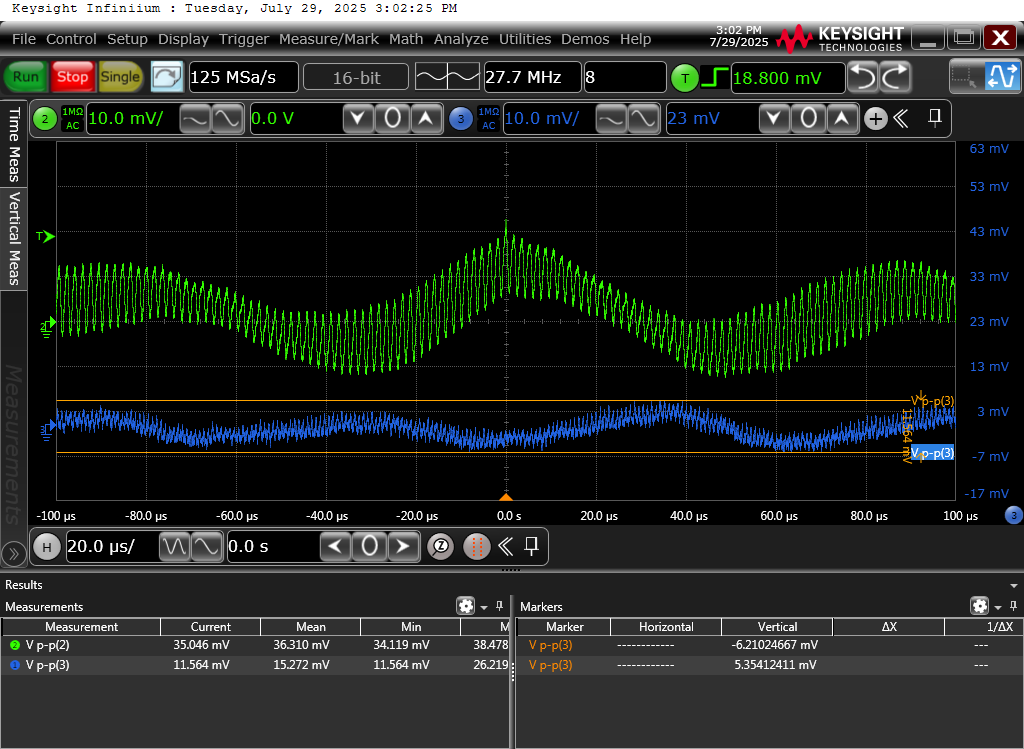
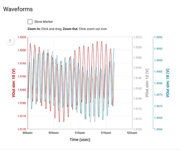
I've measured the output voltage ripple of the TPS54318. Besides the switching noise of around 8mV_pp there is a beat frequency of around 12 kHz which increases the overall output voltage deviation to 16mV_pp. 

Is this due to the internal voltage regulation?

Thank you. 

Kind regards

Moritz


  • Hi Moritz,

    My feeling is that it's probably related to the compensation. Can you run a bode plot to check the cross over frequency and phase margin?

    You can experiment changing R3 and C4 in your schematic to 2.8K and 2.1nF. If this doesn't help then you can also try with C9 disconnected.

    If this is for a new project, I would recommend our newer TPS628303, TPS628513 or TPS628503.

    Best regards,

    Varun

  • Hi Varun, 

    thank you for your idea regarding the compensation network. It is from a existing design and does not seem to be ideal. I checked it quickly in Webench and it did not throw any errors back then. I am not able to plot them together in Pspice:
    This is the schematic:

    here is your recommendation (ZeroCross(db(v(vout)))    42.78321k  PhaseMargin(db(v(vout)),P(V(vout)))-180    18.66257 Max(db(v(vout)))    60.55988)

    Vs the current design: (ZeroCross(db(v(vout)))    1.17147k PhaseMargin(db(v(vout)),P(V(vout)))-180    91.32958 Max(db(v(vout)))    21.21028)


    Vs. the webench Tool


    Might the limited zero crossing BW the issue here?
    I am going to do some measurements in a couple of days, with the modified design. 

    Kind regards

    Moritz

  • Hi Moritz,

    Thanks for running the sims and summarizing. I see the C4 value I recommended was too low. The value needs to be higher like what Webench recommends so that the zero from R3 and C4 comes in at a lower frequency and gives a phase boost. 

    With the current compensation you have on your board, the cross over is quite low. However the phase margin looks good. It could be that the PSRR of the device is low at higher frequencies due to the low bandwidth. Can you also check on the input supply if it has any noise at 12KHz? If it has, it might be passing through to the output without much attenuation.

    Best regards,

    Varun

  • Hi Varun, 

    thank you very much. You had the right hunch. The 5V input supply is already a bit noisy.
    However, the PSRR is not defined in the datasheet of the TPS54318. I am a bit surprised that it is only around -10dB at 12 kHz.

    It is lower than the LC Cutoff ( 1/2*pi*SQRT(LC) ~ 22.9 kHz ) for 22uF and 2.2uH.


    Kind regards

    Moritz

  • Hi Moritz,

    Thanks for measuring and confirming that. The PSRR depends on the bandwidth and the output LC used. Currently 12KHz is falling into a region where the LC is not effective and there is no bandwidth from the DC-DC.

    You can try increasing the bandwidth by changing the compensation values. This should improve PSRR.

    Best regards,

    Varun

  • Hi Varun, thank you for the explanation. 

  • Hi Varun, 

    I was playing around with the values in Webench when I noticed, there is some kind of beat frequency visible as well. 

    This usually independent of the values for the type II compensation. Is this some kind of artifact from the current mode control?

    Kind regards

    Moritz

  • Hi Moritz,

    My feeling is that this oscillation is just related to the implementation of the Pspice transient model. I can check if I have an EVM of this part and then test it in the lab. 

    Where you able to check if the noise is better attenuated with the new compensation settings?

    Best regards,

    Varun

  • Hi Varun, 

    thank you for the update. Regarding the Pspice Modles:
    Is there any reason the models are so slow. Compared to the company from Wilmington it is really hard to work with them. Let alone sweep something. 

    It was no help that PSpice for TI just stopped working for  the last two days. (e2e.ti.com/.../5956366)


    I am going to modify the PCB next week and share the measurements. 

    Kind regards

    Moritz

  • Hi Moritz,

    For our newer parts, we offer a SIMPLIS model in addition to SPICE which should simulate startup is less than a minute. Steady state and AC sims run even faster. For the older parts, unfortunately I don't see any other option than using Pspice for TI.

    I don't have a TPS54318 IC. I shall order one just in case you still see issues after your PCB testing next week.

    Best regards,

    Varun 

  • Hi Varun, 

    I adjusted the compensation to C4 = 10nF , R3 = 3.3k. C5 = NC. 
    Which results according to PSpice in: 

                                                             I out            1mA               250mA         500mA           1A

    1    ZeroCross(db(v(vout)))                                  49.37155k    49.26705k    49.13860k    48.81179k
    1    PhaseMargin(db(v(vout)),P(V(vout)))-180     46.47387      48.11527      49.77591      53.13878
    1    Max(db(v(vout)))                                            48.79627      47.89899      47.08292      45.65075
                       

    I tried to maximize the BW to reduce overshoot. 

    The beat frequency was also reduced to 10mV (before 16mV), which shows the PSRR was increased by increasing the loop BW. 

  • Hi Moritz,

    Thanks for the update. Is the attenuation achieved with the new settings sufficient for you?

    Best regards,

    Varun

  • Hi Varun, 

    yes it is now close enough to the ripple. 

    The previous oscillating stage needs to fixed though. 

    Thank you very much for your help. 

    Kind regars

    Moritz

  • Hi Mortiz,

    Understood. I shall go ahead and close this thread.

    You can comment again if you need to open it.

    Best regards,

    Varun