This thread has been locked.

If you have a related question, please click the "Ask a related question" button in the top right corner. The newly created question will be automatically linked to this question.

BQ25756: REGN voltage is too low

Part Number: BQ25756

Tool/software:

Hello, 

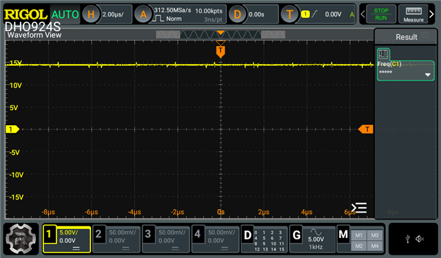
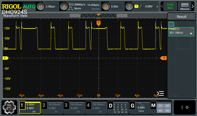
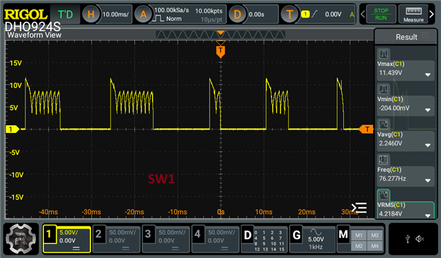
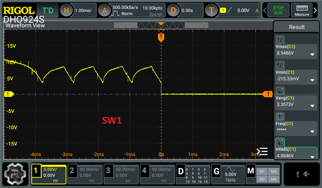
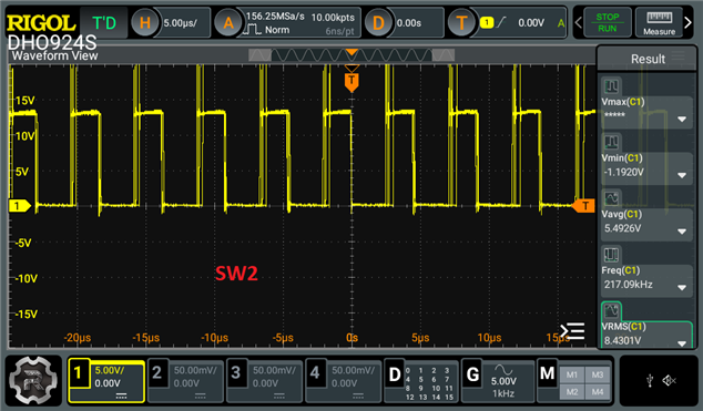
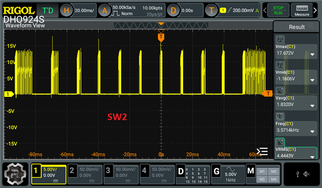
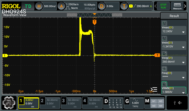
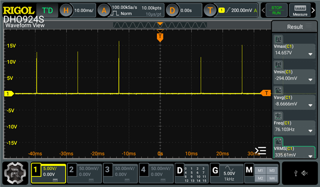
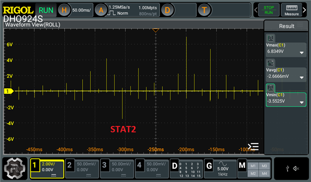
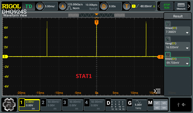
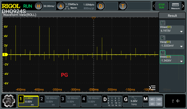
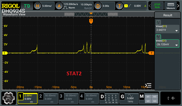
I am using BQ25756 chip to charge the battery without I2C (in stand alone mode). Vregn when I measure is 1.6V. Both STAT outputs are at GND and CE pin is held low (GND).

Maybe you could view the schematics and maybe you will see some kind of problem. Maybe you need some more measurements. When I power the charger it draws about 15 mAcharger_Schematic.pdf

In this scenario there is no charging happening (I think its obvious but I will mention it).

  • Hi,

    REGN should not be used to power additional components. It does not have a large current capability. REGN is for the TS thermistor network and the gate drive. What is the voltage on REGN if you disconnect the SN74LVC1G19DCKR?

    Additionally, I would not recommend connecting REGN to the I2C communication lines. REGN will turn off when the charger is in battery only line.

    Also, the TS pin voltage sense is referenced to percentages of REGN, using 12 V here could affect what temperature region the charger sees compared to what the battery actually is.

    Best regards,
    Michael

  • Thank you,

    When disconnected SN74... REGN voltage is 5V. I also referenced thermistor to REGN pin

    Now charging starts, but inductor heats up to 90 degrees when charge voltage is set to 1.6A and it draws 5.24A from supply (it is max supply current) and supply voltage drops to 6V. When connecting two power supplies in parallel current consumption becomes 10.48A and voltage is still 6V. Charge current at that time becomes 3.2A.

    Changing switching freq doesn't help (tried changing it from 450 Khz to 600 Khz).

    What do you think can lead to this behavior? Could inductor be wring for this charger?

  • Hi,

    I looked at the datasheet for the inductor PA5432.103NLT. It seems like this inductor should work with the BQ25756. I think part of the issue may be the MOSFET selection. This MOSFET has a Coss of 1200 pF. In section 9.2.1.2.8, the datasheet states: "It is recommended to limit the total switch node capacitance CSW (nF) < 160/VIN; for example, for a 60-V application, it is recommended to keep the total CSW < 2.67 nF." Does the behavior improve at all when using a MOSFET with a lower output capacitance?

    What is your input and output voltage conditions?

    Additionally, can you provide waveforms of SW1, SW2, and the input/output current?

    Best regards,
    Michael Bradbourne

  • Hello, I don't have more MOSFETS on me, but I will order more.

    I will try MOSFETS suggested in datasheet of BQ25756

    Input voltage is 12V and output voltage is 12.6V.

    SW1

    SW2

  • Hi,

    Let me know if the new MOSFET has any improvement. The waveforms shown do not look like what I expect for 12V in and 12.6V out.

    In the meantime, can you use the ADC to measure the input current and output current? The current draw of 5 A should not happen under these conditions when charge current is limited by hardware to 1.6 A. I wonder if there is a short anywhere on the board.

    Best regards,
    Michael

  • Hello,

    I changed MOSFETS to AONS66614CT and inductor to IHLP6767GZER100M01. Situation is a little bit better, but far from ok.

    I shorted I_LIM_HIZ to gnd and know when I try to charge with input voltage of 12V I am not getting any current in output. But when I lower input voltage to 5V charging is working, but it draws 4,7 A from power supply (charging current is 1,6A, so 5W loss).

    When charging is not working I can hear inductor sound and when I lower input voltage sound disappears (or at least I can't hear it).

    Before that I soldered 8k resistor to gnd on ILIM_HIZ pin and when I tried charging, it was drawing current from 0A to 3,5A (it fluctuated all the time). After some time current always dropped to 0,2 A ( from power supply) and there was no charging. At all times I can hear inductor making sounds. Do you have any suggestions?

  • Hi,

    Was there any current drawn from the input when there was 12 V input supply? There might be a short circuit somewhere that is causing the power loss. Do your registers report anything in the status, fault, and flag registers? Can you provide waveforms of the input/output current and the SW nodes?

    Best regards,
    Michael

  • Hello,

    Input current is fluctuating between 1A and 2,5A at 12 V input (I can't provide input/output current at the moment, but maybe you could help me with this information). There is no short circuit. REGN is 5 V at all times. STAT1 ON (pulled low). STAT2 is off

    SW1


    SW2:


    After some time (few minutes) current from power supply drops to 200 mA (not fluctuating) and noise from inductor changes. At this moment STAT1 and STAT2 and PG is pulled low (to GND). Inductor continuous to heat up (60-70 degrees). SW2 at that time:

    Could something like this be caused by badly routed PCB? Inductor and FETS are from reference design at this moment

  • Hi,

    REGN is 5 V at all times. STAT1 ON (pulled low). STAT2 is off

    Was this confirmed by a waveform? STAT1 and STAT2 could be flickering faster than the eye can see. Based on these waveforms, the charger is beginning to charge and then stopping charge. This keeps happening repeatedly.

    At this moment STAT1 and STAT2 and PG is pulled low (to GND)

    Was PG not pulled low before? STAT1 and STAT2 being low indicates a charging fault. Can you read via I2C what this fault is. This would be in registers 0x21 to 0x27.

    Inductor continuous to heat up (60-70 degrees)

    This implies to me that there is current flowing through the inductor. The input current is 200mA. Is there any current from the output supply? What is the output in this instance btw? Is it a battery?

    Could something like this be caused by badly routed PCB?

    I would say this might be possible, but nothing has indicated a PCB issue to me yet. Have you tried to perform a swap with an EVM?

    Best regards,
    Michael

  • "Was this confirmed by a waveform? STAT1 and STAT2 could be flickering faster than the eye can see. Based on these waveforms, the charger is beginning to charge and then stopping charge. This keeps happening repeatedly."

    I took waveforms of PG, STAT1/2 when input current drops to 200mA and charging stops:


    This is status pins waveforms when some kind of charging happens and input and output current fluctuates (previous message first 4 waveforms):

    "Was PG not pulled low before? STAT1 and STAT2 being low indicates a charging fault. Can you read via I2C what this fault is. This would be in registers 0x21 to 0x27." 

    PG is always pulled low. I am trying to design this to work in standby mode, but if nothing else helps I will try to read these registers this week.

    "This implies to me that there is current flowing through the inductor. The input current is 200mA. Is there any current from the output supply? What is the output in this instance btw? Is it a battery?"

    Yes there is. when input current fluctuates, output current fluctuates respectively, between 0,5A and 2A (BQ is configured to output 1,6A). As I mentioned before, when I lower input voltage to 5-6V, charging becomes stable at 1,6A, but input current is 5A. There is a battery at the output

    "I would say this might be possible, but nothing has indicated a PCB issue to me yet. Have you tried to perform a swap with an EVM?"

    What do you mean swap with EVM? I tried EVM and it works perfect on same PCB, just bypassing current BQ charger part

  • Hi,

    I am trying to design this to work in standby mode, but if nothing else helps I will try to read these registers this week.

    That makes sense. I2C would be helpful for debugging though. The simultaneous on states of STAT1 and STAT2 indicate a charging fault, but I won't know which one or what to look at without access to the registers.

    As I mentioned before, when I lower input voltage to 5-6V, charging becomes stable at 1,6A, but input current is 5A. There is a battery at the output

    This seems that the boost mode is more stable. The output voltage is 12.6 here, correct? That should be 4 A max on the input based on the charge current. If boost mode is more stable, I think the issue may be related to the SW1 side of the board. The SW1 waveform also looks incorrect on the scope screenshots. Can you check the FETs for any shorts from Gate to Drain, Gate to Source, Drain to Source? It would also be helpful to make sure that the BTST1 circuit is working properly here.

    What do you mean swap with EVM? I tried EVM and it works perfect on same PCB, just bypassing current BQ charger part

    I just mean to say to make sure the IC isn't damaged or anything. An ABA swap of the good EVM IC with the board IC could let us know if the IC has been damaged.

    Best regards,
    Michael

  • I tried reading REG0x21 via I2C

    I saw that charge status is changing between "Not charging" and "Fast charge". There is no errors at the time.

    Maybe I could read more registers to help you understand my problem?

  • Hi,

    The best registers to read would be all of 0x21 to 0x27. This should give the full device status and faults.

    Best regards,
    Michael

  • Hello,

    The only fault flag which is being set is over-voltage flag in register 0x27. This fault persist even when there is no load connected (no battery)

  • I forgot to mention it, but drive supply pin fault is being triggered too

  • The overvoltage flag will be set until the host reads it from the register. Does that flag continuously get set without the battery?

    DRV_SUP fault implies that the DRV_SUP pin is behaving improperly. Have you seen any odd behavior on the waveform? From the schematic it is tied directly to REGN, and you said the REGN voltage was stable at 5V now.

    Best,
    Michael