This thread has been locked.

If you have a related question, please click the "Ask a related question" button in the top right corner. The newly created question will be automatically linked to this question.

LM5146: Switching stops after soft-start is complete

Part Number: LM5146

Tool/software:

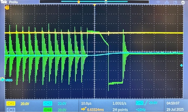
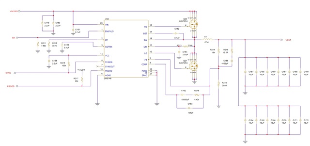
Hi, I'm having trouble getting an LM5146 circuit to work as I want. My setup has Vin=100V and Vout=52V, SYNCIN pulled high, and no load during power-up. About N ms after the output reaches the target voltage, switching stops and the output decays down to 0V. I'm operating under the assumption that the LM5146 is stable in DCM and goes unstable as it transitions to FPWM, but based off the quickstart calculator I would expect it to be stable, but I've reached the end of my expertise. Could anyone please assist?

Thanks

LM5146_quickstart_calculator_revB1_100V-52V_300kHz_r3.xlsx

Startup Waveform with Vin = Yellow, Vout = Blue, SW = Green

  • Hi Eric,

    There is an internal 20kΩ pulldown on SYNCIN, so a 100kΩ pullup shown on the schematic means there is a low voltage on the pin....too low to set FPWM. If you're at no load, switching will stop until Vout falls. Try tying SYNCIN directly to VCC.

    Regards,

    Tim

  • PS: 100V input is right at the max rating for this controller. Also, the output current is quite high, and I can see the SW voltage well above 100V in your scope shot.

    Looking at the quickstart, your full-load rating is 18A, yet current limit setpoint is 9.6A. Current limit is typically 120-130% of full load. The Rdson of the FET is vert high for this current level, which is why the efficiency curve is not converging in the quickstart. Also, the inductor DCR at 19.2mΩ causes huge power loss, Try lower inductance to get lower DCR and better overall losses.

  • Btw, the last part of the SW waveform looks very unusual, where the high-side FET stays on for 10us, then the voltage falls....what is the inductor sat current? Better to use a powdered iron core inductor with soft sat here.

  • Tim,

    Good to know about the SYNCIN pulldown and good point about the 100V input. I'll drop VIN down to 85V as some of the strange behavior I've been seeing could be caused by damage to the components.

    The 18A IOUT_MAX is probably a bit too aggressive: for some additional context, my load is pulsed on for about 100ms and then turned off for >1000ms with an RMS current draw of about 6A. Heat dissipation hasn't been a large concern even with the high Rdson and inductor DCR due to the low duty cycle, but I'll revisit the inductor and FET selection.

    The inductor sat current is 12A and is a MnZn ferrite core.

    One configuration that I'd like to use would have an external clock drive SYNCIN; would there be any issues with driving the SYNCIN pin prior to providing VIN or VCC?

    Thanks,
    Eric

  • No, should be fine.

  • I replaced the LM5146 with a new one, dropped the input voltage slightly and added a 2 Ohm Rboot resistor.  This has resolved the unexpected behavior in the original post, so I suspect the root of the issue was that the overly high voltage on the SW node had damaged the LM5146 I was using.  

  • Okay, thanks for the update.