This thread has been locked.

If you have a related question, please click the "Ask a related question" button in the top right corner. The newly created question will be automatically linked to this question.

TPS61094EVM-066: The measured output ripple is larger than theoretical calculated value

Part Number: TPS61094EVM-066
Other Parts Discussed in Thread: TPS61094

Tool/software:

Hi experts,

The theoretical value of Vout,ripple doesn’t match the measured result when I use TPS61094 EVM to run the test of Figure8-2 from datasheet(TPS61094 60-nA Quiescent Current Boost Converter with Supercap Management datasheet (Rev. C)).

The test condition is set Vout and Vin unchanged, increasing Iout by adjusting E-load, and get Vout,ripple from different load cases.

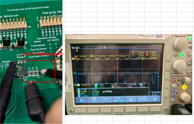
Measurement setup looks like this:

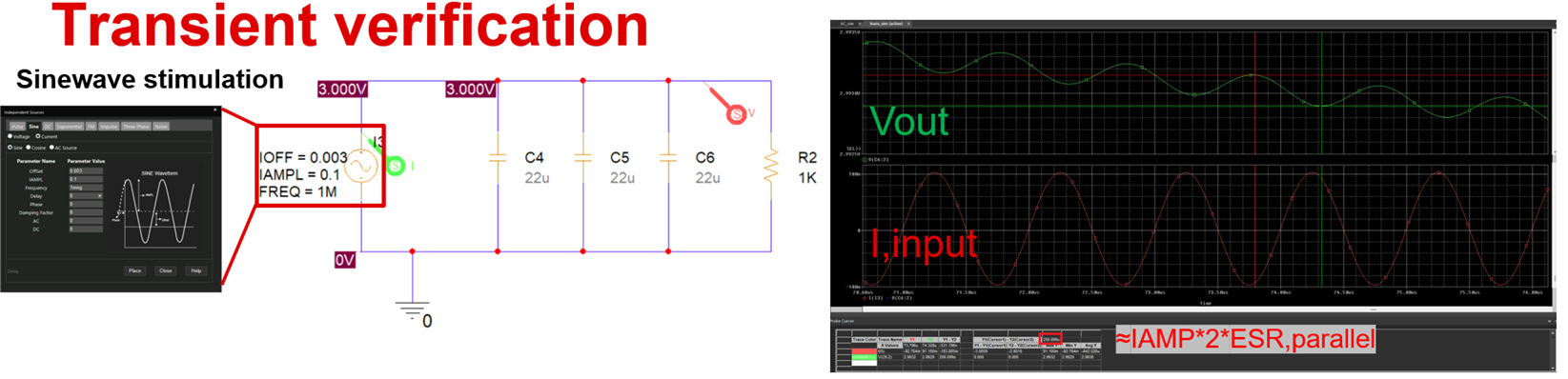
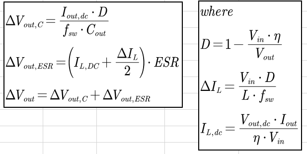
The vout,ripple formula derivation ref source is Basic Calculation of a Boost Converter's Power Stage (Rev. D)

Below is the measured result:

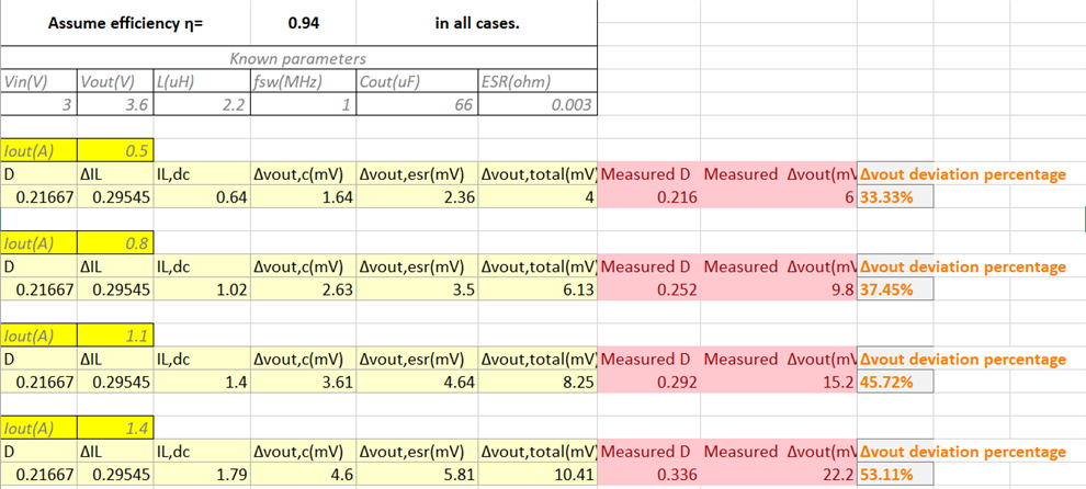
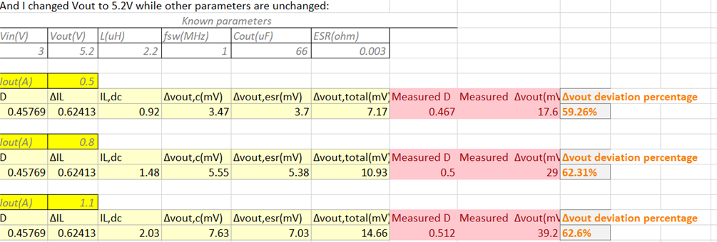
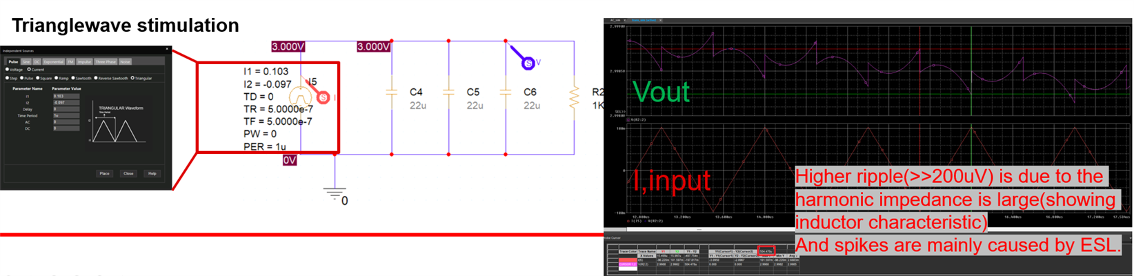
How to explain the deviation between measured result and theoretical Vout,ripple value, especially when Iout increasing?

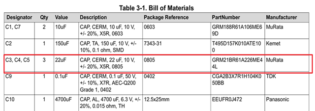
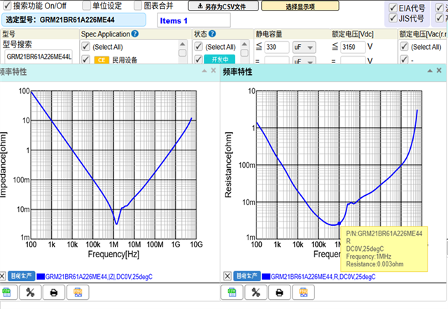
Another thing is, the Cout that used in EVM is operating at the self-oscillating point where fsw is about 1MHz in TPS61094, so Cout should now be treated as a pure R with magnitude of ESR, there will be no Δvout on C, just Δvout on ESR, then the deviation escalates.

Looking forward to your reply.

Best Regards,

Ethan

  • Hi Ethan,

    The major deviation comes from the difference between the marked capacitance and the effective capacitance. 

    Consider the capacitance loss from the DC biasing and AC ripples, the total effective output capacitance is around 50% left, that is, 33μF, not 66μF.

    And regarding the self-oscillating point, although close the the 1MHz, it's still bigger than 1MHz and the the capacitor model is still there.

    Regards

    Lei

  • Hi Lei

    Thanks for the quick response! I agree about your opinion about the 50% cap loss(when operating at DC & low frequency). But when comes to fsw frequency, which happens to be or close to the self-oscillation point of the cap, the reactance is quite small due to ESL and cap are cancelling each other's contribution to reactance, although it still could be considered as a cap model C' with Z=ESR-j/wC', the equivalent capacitance value C' is much more larger than the original value 33uF(when at the oscillation freq, the value is +infinity and cap is now a pure resistor).


    So in my opinion, when cap operating near self-osc frequency, vout,ripple that contributed by cap is small due to the large equivalent cap value, and the deviation still exist. And I do think that choosing the self-osc frequency of output capacitance near the switching frequency of converter is a good thing for design, since the AC impedance is so small.

    Correct me if I'm wrong, and thank you for your time.

    Best Regards

    Ethan

  • Hi Ethan,

    Here is my understanding for your reference.

    In all frequency ranges, the cap can be modeled as cap + resistor + inductor.

    So even at the self-oscillation point, for a output capacitor, it's capacitance is still there. There will still be charge and discharge current on the cap, so is the ripple caused by the cap. 

    Regards

    Lei


  • Hi Lei,

    Again I want to thank you for the response.

    Here is my understanding of this question.

    Surely the current flow through the cap cause charge & discharge ripple, the phase of ripple,c is 90° lagging the current --- Vripple,c=I(t)/jwC. But the current also flow through the serial parasitic inductor and cause ripple,L, which is 90° leading the phase of current --- Vripple,L=I(t)*jwL. The output ripple Vout,ripple=Vripple,c+Vripple,L+Vripple,R, the Vripple,c and Vripple,L are cancelling each other due to the 180° phase shift, and the summation of these two reaches to 0V when at self-oscillation frequency, only Vripple,R left in the equation.

    Thank you for your support!

    Best Regards,

    Ethan

  • Hi Ethan,

    Let me check and reply to you a little later.

    Regards

    Lei

  • Hi Ethan,

    Thank you for your information.

    I totally agree with you! You calculation seems the one what we're very familiar with. Well, the real Vout ripple should be much bigger even when the switching frequency is right the self-oscillation frequency. Just let me try to find out where is going "wrong". It's an interesting questionGrinning

    Regards

    Lei

  • Hi Lei,

    Glad you find this topic interesting. Looking forward to your reply!

    Best Regards,

    Ethan

  • Hi Ethan,

    Let's further discuss early next week.

    Regards

    Lei

  • Hi Ethan,

    Although I don't have a thorough explanation yet, here are some comments for your reference first.

    For the C + R + L model of a capacitor, if the driving supply is a pure sin or cos signal of which the frequency is the self-oscillation frequency of the L and C, then as what you said, the total voltage on the capacitor will be contributed by the R (ESR) only.

    Well, if the driving supply is a triangle signal, even its frequency is also the self-oscillation frequency of the L and C, there will still be signals in frequency other than the self-oscillation frequency, so the total voltage on the capacitor will be contributed by the C + R + L.

    And for the Vout ripple, it's better to analyze in the time domain. The total Vout ripple is not a simple sum of the amplitude of each frequency component. 

    Just let me know if you have any other thoughts.

    Regards

    Lei 

  • Hi Lei,

    Totally agree with you on this. The impact caused by higher harmonic frequency is not considered in my previous analysis. I set up the equivalent output node circuit in PSpice, simply a current source to simulate the current flow to output, and three parallel C(model inside connected with a 3mOhm ESR and a ESL to set self-oscillation freq at 1MHz), then I ran the transient sim to get the Vout waveform.

    When I,input is single-frequency sinewave, the value of output ripple is basically ESR*I(p-p), that's when C can be considered as a pure resistor.
    When I,input is a triangle wave(that's a good approximation for Buck, but the current is more complicate than a triangle wave for Boost), the output ripple is much larger than sinewave scenario due to harmonic frequencies are introduced here, the impedance is now dominated by ESL, and spikes occurs(I think it's also caused by ESL).

    Appreciate the support! Thanks for joining the discussion of this trivial question.

    Best Regards,

    Ethan

  • Hi Ethan,

    Welcome!. Thanks for providing the simulation results.

    I'm glad that we can make this interesting question clear togetherGrinning

    Regards

    Lei