Tool/software:
Hi
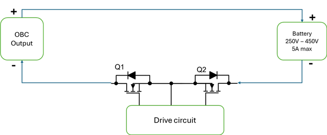
I want to use the battery cut off circuit in Ground path with 400V battery, please suggest the application circuit or driver circuit for that.
Configuration: Back-to-back MOSFETs with common drain or Common source.
Original question:

Tool/software:
Hi
I want to use the battery cut off circuit in Ground path with 400V battery, please suggest the application circuit or driver circuit for that.
Configuration: Back-to-back MOSFETs with common drain or Common source.