This thread has been locked.

If you have a related question, please click the "Ask a related question" button in the top right corner. The newly created question will be automatically linked to this question.

TPS389006Q1EVM: Can TPS389006Q1EVM used for testing TPS388008001 ? How does TPS389006Q1EVM detect and recognize a supervisor reference?

Part Number: TPS389006Q1EVM
Other Parts Discussed in Thread: TPS388008, TPS389006

Tool/software:

Hi everyone,

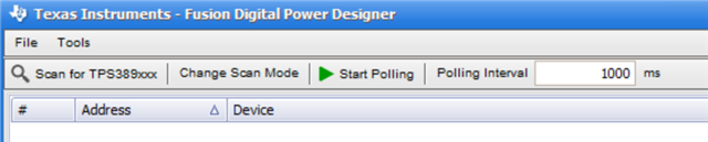
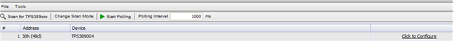
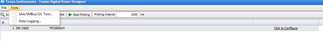
Recently, we did a monitoring test with a TPS388008001 and the evaluation board TPS389006Q1EVM on the software device TI Fusion Power Designer 7.6.6. I change the jumper's configuration to adapt TPS389006Q1EVM to TPS388008001.

Unfortunately, the software device can't recognize the TPS388008001. In fact, he detected the TPS389004 but we didn't have this component and we didn't have 4 monitoring channel but 8. So, we had to take the supervisor TPS389006 because we thinked that the probleme came to the fact that TPS388008 didn't adapt for our evaluation board. But, the software device detected again the supervisor TPS389004. So we want to know why the evaluation board TPS389006 can't recognize the good version of supervisor ?

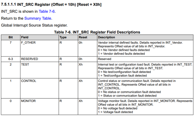
Finally, we did a monitoring test with a TPS388008001, the evaluation board TPS389006Q1EVM and a Micro-Python code to command the supervisor with a Raspberry Pi Pico. We noticed that the supervisor seems to work well but he conserved the past errors of monitoring on this volatile memory until we did a reset of the power supply. So we want to know was it a register who permitted to erase the past errors every time we launch the code ?

  • Hi Issa,

    Were you able to read and write to the TPS388008001 when using TI Fusion Power Designer? It is possible that the software just shows the wrong name for the device.

    For your second question, the device has a latched output, which is why you continued to see the errors until resetting the power supply. You can unlatch NIRQ by performing a write one to clear operation while also removing the fault condition, or performing a power cycle.

    -Henry

  • Hi Henry,

    Thanks for your answer.

    In fact, I can write on the TPS388008001 but not in the monitoring channel 5, 6, 7 and 8 like the software shows the wrong reference. For the read, I don't know where I can see the reading of the register that I use on the software. Also, I had probleme with the adjustment of the scalling setting. I can choice the scalling x4 or x1 for OV threshold but I can't choise the scalling x4 for UV threshold.

  • Hi Issa,

    The scaling setting on both TPS38800x and TPS38900x sets the scale for monitoring as a whole, there is no individual setting for UV/OV.

    Could you provide a screenshot of the TI Fusion Digital Power Designer window? Do you see something like this in the scan mode?

    Also, could you please provide the exact commands/sequence you are doing to read/write to the device? Which bank, register, etc. you are interacting with.

    -Henry

  • Hi Henry,

    I'm come back from hollidays. I have this window that appears like you:

    At beginnig, I set the commands on this pages just for scalling, monitoring channel and threshold:

    After, I seen an other window in which I can set each register with byte code. Like I noticed the name and the address of the registers on the software device is different that the name  and the address of the registers on component's datasheet, I did a code in MicroPython where I selected BANK 0 at beginning to write on the registers PROT 1, PROT 2 and PROT MON to allow changes.

    After, I selected BANK 1 to make the changes I wanted and I make changes on the registers Vmon_CTL, VMON_MISC, IEN_UVHF, IEN_OVHF, IEN_CONTROL, IEN_VENDOR, MON_CH_EN, VRANGE_MULT, UV_HF1, OV_HF1, FLT_HF1, AMSK_ON, AMSK_OFF, AMSK_EXS and AMSK_ENS.

    Finally, I selected BANK 0 to do reading of the registers INT_SRC, INT_MONITOR, INT_CONTROL, INT_VENDOR, INT_UVHF and INT_OVHF.

    I used the syntaxe "i2c.writeto(device_addr, command)" for the writtting sequences and the syntaxe "i2c.writeto(device_addr, register_addr) + i2c.readfrom(device_addr, nbr_byte)" for the reading sequences like you can see in this part of my code:

    print('Création de la trame PROT2')
    
    Reg_Addr_PROT2 = 0xF2 #Octet contenant l'adresse du registre (Valeur convertie en hexa)
    dataPROT2_WR = 0x00 #Octet contenant la commande que l'on veut passer (Valeur convertie en hexa. 0x00: Changes are possibles. Ici, on souhaite activer la modification par écriture sur chaque registre de BANK1 afin de pouvoir changer des paramètres/commandes)
    tramePROT2 = bytearray([Reg_Addr_PROT2, dataPROT2_WR]) #Création de la trame PROT2
    print(tramePROT2)
    
    i2c.writeto(adr0, tramePROT2) #Envoi de la tramePROT1 à l'adresse de l'esclave
    
    i2c.writeto(adr0, bytes([Reg_Addr_PROT2])) # Sélection du registre à lire
    dataPROT2_R =i2c.readfrom(adr0, 1)
    print("Données lues : ",dataPROT2_R) 
    
    utime.sleep(Tempo) #Temporisation afin de laisser le TPS38800 prendre en compte la commande précédante
    print("\n--------------------------------------------------------------------------------------")

  • Issa,

    Currently TI Fusion Digital Power Designer does not fully support TPS38800x devices, and instead shows the configuration page for TPS389xxx devices. The name of the registers in the software do not correctly map to their actual addresses, as TPS38800x and TPS389xxx have different register maps. The only way to properly configure the device using TI Fusion Digital Power Designer at this time is to use the SAA/SMBus/I2C Tool and manually configuring the registers.

    -Henry

  • Hi Henry,

    Thanks for your help. I noticed that the write operations are better with this method like the read operation and, this time, I can see every command that is being read. There is one last problem. During my last test, I saw that there is a fault of state or communication detected on the INT_SRC register. I want to know where the problem might come from?

  • Hi Issa,

    To clarify, are you able to read the contents of the register properly or is there an error when trying to read from only this register? If you cannot read from the register using TI Fusion Digital Power Designer, please send a screenshot of the error you are encountering.

    The INT_SRC register stores information about the source of a global interrupt, and is described fully in section 7.5.1.1.1 of the datasheet.

    -Henry

  • In fact, I can read in this register but I set a voltage 0 V on channel 1 with an under-voltage threshold at 3.1 V. However, I do not read on the software a failure of the voltage monitor in the register INT_SRC because I have the data code 02h. I read this data code in this area:

    Instead of the 0x00 you see on the current image, there was 0x02 which means that there are no voltage monitor defects but status or communication defects. This is this data code who surprise me.

  • Issa,

    Per the datasheet, the details of a control interrupt are reported in the INT_CONTROL register. INT_CONTROL will explain why the interrupt was triggered.

    An under-voltage interrupt will not be generated by an under-voltage fault if the interrupt is not enabled, or if the channel monitoring is disabled. The datasheet explains the exact conditions required for generating an interrupt.

    -Henry