


Tool/software:
Hello
We are designing a four-cell BMS in series for INR-21700-P50B. Our application requires a 25A discharge for a few seconds. By performing some tests with a digital load, I can successfully apply a 23A discharge, but when I increase the discharge to 25A, it's as if the BQ40Z50-R5 cuts off the power for some reason I haven't been able to discover (all protections are disabled for testing purposes).
With a 23A load, the voltage drop across the battery connector is only 1.5V. I'm using two 1.5mR MOSFETs in parallel for DSG and CHG.
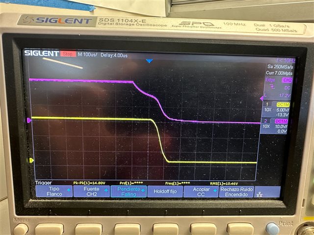
Below is an image captured by the oscilloscope, where purple is Vgate DSG and yellow is Vpack. Here you can see that the BQ40Z50-R5 turns off the discharge MOSFET when a 25A load is applied.
I also attach images of tests applying different currents and observing the voltage drop to ensure that the voltage is not dropping more than necessary. In the graph you can see when a satisfactory discharge is applied, the current line is maintained for a few seconds, where the line fluctuates is a failed discharge at 25A.


