Other Parts Discussed in Thread: , BQSTUDIO
Tool/software:
Dear Sirs and Madams,
We are in the process of evaluating the BQ25792 and have a question regarding charging current.
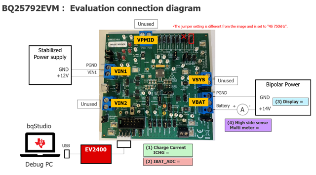
The configurations being evaluated are as follows:
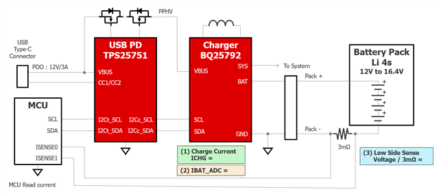
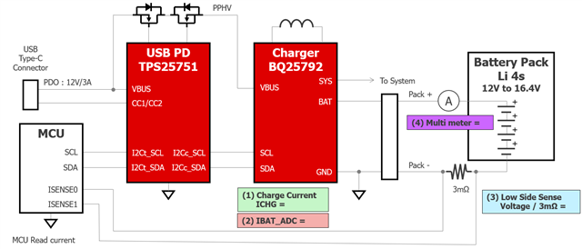
Input of BQ25792 : 12V
Load : The evaluation was performed using a constant voltage(CV) of 14.4V instead of an actual 4-cell battery.
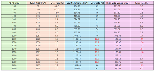
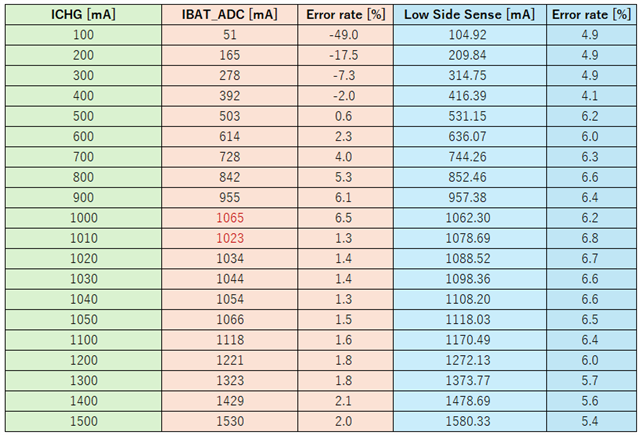
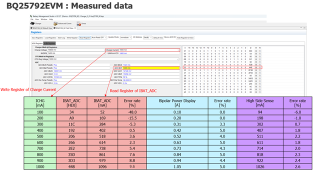
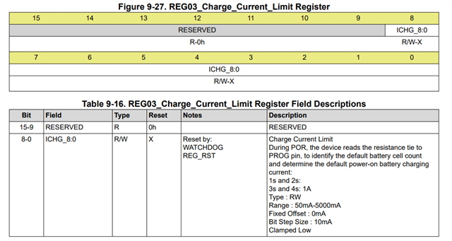
(1) Setting the charging current (ICHG) of the BQ25792.
(2) Read the charging current value (IBAT_ADC) of BQ25792.
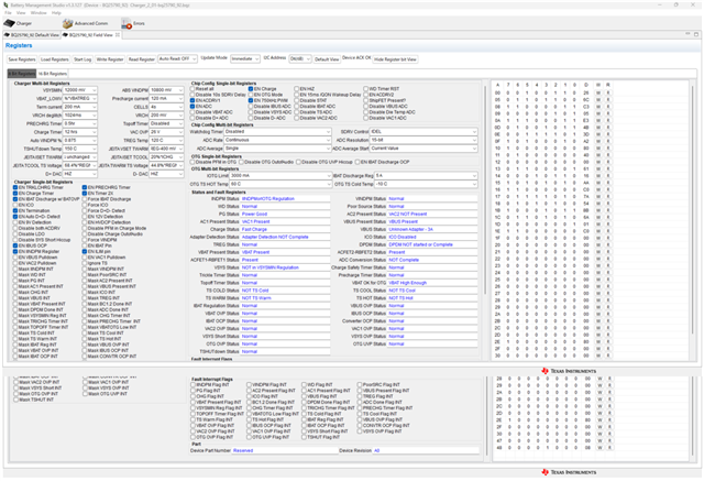
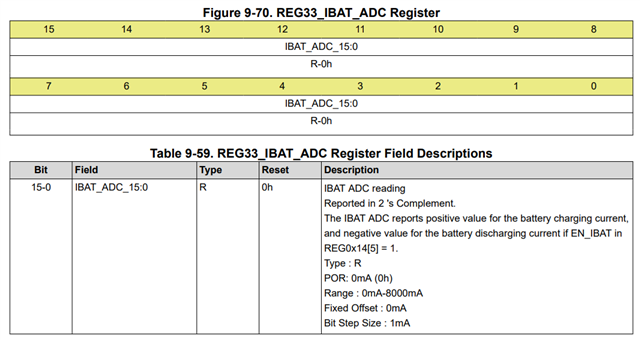
The ADC resolution is set to 15 bits (0h) for ADC_SAMPLE_1:0 of REG2E_ADC_Control Register.
(3) The battery current is the Low Side Sense, and the actual current value is calculated by measuring the voltage across the sense resistor.
Then, We compared ICHG, IBAT_ADC and Low Side Sense.
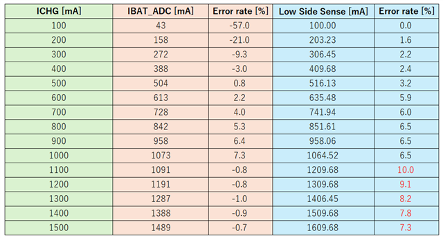
/* Measurement sample A */
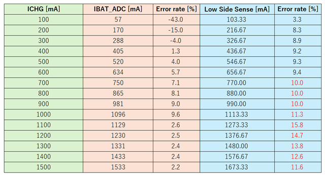
/* Measurement sample B */
[Question1.]
We can see that the current actually flowing through the battery (Low Side Sense) is higher than the current value set (ICHG) by the BQ25792.
The error seems to be particularly large when the charging current setting is high.
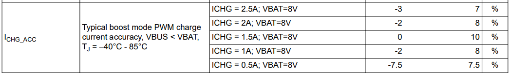
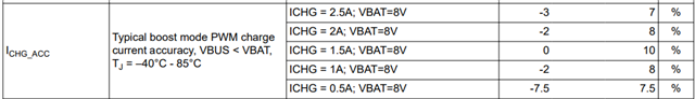
The datasheet specifies the current accuracy when charging a 2cells battery in boost mode, but does the accuracy tend to be worse than the specified accuracy when charging 4 cells?
[Question 2.]
It can be seen that the set charging current (ICHG) and the battery charging current read by the ADC (IBAT_ADC) show similar values.
Where does the IBAT_ADC of the BQ25792 measure the current flowing through?
I checked the datasheet but it doesn't seem to be mentioned.
[Question 3.]
We think 10% to 15% error is too big.
Do you know how to improve these?
Regards,
Masashi