This thread has been locked.

If you have a related question, please click the "Ask a related question" button in the top right corner. The newly created question will be automatically linked to this question.

BQ34Z100-R2: How to create the "simplest working version" for a test board

Part Number: BQ34Z100-R2

Tool/software:

Hello, 
I am looking to create a coulomb counter for a PCB I am working on, and this is the only IC which seems to be able to work for it, since it:

  • Uses 2 cells in series
  • Uses LiFePO4 chemistry
  • has a very large capacity (~300Ah)

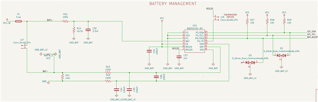
This means that the battery voltage will be 6.4V, so I have calculated the voltage divider resistor to be 100kΩ.

The schematic I have designed is heavily base on both the "Multi-Cell and 5-LED Display" from the datasheet, as well as the EVM board schematic, and this post on the E2E forums. From these sources, I have created this schematic:

There are a few things to note about this schematic:

  1. GND is common for the rest of the circuit board, and is shared by a lot of different components. 
  2. VCC is 3V3 and comes from a linear regulator. It will be supplied by the battery.
  3. GND_BAT is ONLY used for the battery, and is equivalent to "AGND" from the datasheet (I have renamed it since I already have an AGND)

My questions are as follows:

  1. Should GND or GND_BAT be connected to BAT-? On the datasheet it appears to be both, which I do not understand
  2. How do I connect the rest of my system? I assume from the datasheet that BAT+ goes to Vin (supply for linear regulator) and that my system ground connects to "PACK-" , but this doesn't make sense following Question 1, since then both BAT- and PACK- are connected to ground and no current will flow through R11 and it seems pointless.
  3. Are there any obvious mistakes I have made for the connection of the system, and am I missing any critical components?

Thankyou!

John

  • As a follow up, since I think I understand it a LITTLE more now:

    Should I connect "GND" and "GND_BAT" together for this chip, and have one as high current and the other as low current, and then have an entirely separate "device_ground" which connects to PACK- and is the ground plane for the entire system?

  • Hello John,

    This question has been assigned and will be reviewed when possible.

    Thank you,
    Alan

  • Hi,

    34z100 does not balance cells, if you are using this device with multiple cells in series you need an external monitor to balance the cells. Other gauges can balance cells and gauge them.

    Should GND or GND_BAT be connected to BAT-? On the datasheet it appears to be both, which I do not understand

    both

    How do I connect the rest of my system? I assume from the datasheet that BAT+ goes to Vin (supply for linear regulator) and that my system ground connects to "PACK-" , but this doesn't make sense following Question 1, since then both BAT- and PACK- are connected to ground and no current will flow through R11 and it seems pointless.

    I do not understand the question, BAT+ is connected to BAT. Pack - should not be connected to GND.  Mayve this will help. PMP23329 reference design | TI.com

    Are there any obvious mistakes I have made for the connection of the system, and am I missing any critical components?

    I don't see any other obvious errors.

    Regards,

    Diego

  • Hello Diego, 

    Thankyou for the quick reply! I have modified my system to look like this:

    Firstly, I'll just say that at this stage I am not after a balancing system. If this is foolish, it can be fixed later but for now I am simply after a minimal product.

    As per the datasheets, I have TWO grounds for the battery; "GND_BAT" and "GND_BAT_LC". These grounds are the low and high current ground mentioned in the datasheet. 

    For the rest of my system, I have the positive terminals of the battery connected to VCC_IN which is my system input, and I have the "GND" of my system connected to what was previously PACK-. This "GND" is connected to "GND_BAT" and "GND_BAT_LC" through the sense resistor. 

    The reference design you linked truthfully raised more questions for me than it answered, but I feel as though I am on the right track here so will continue along this path for now. 

    Does the system I have presented seem correct?

    Thanks!

  • Hello john,

    Diego is currently out of office till late next week, please give time for a follow up. We will try to internally follow up this issue until he's back in office

    Thank you,
    Alan

  • Hi,

    Firstly, I'll just say that at this stage I am not after a balancing system. If this is foolish, it can be fixed later but for now I am simply after a minimal product.

    Gauging unbalance cells can add additional errors to the SOC reading. Using this device without a cell balancing monitor is not how the device was intended to be used.  

    GND is connected to the negative terminal of the load?

    if so, I see no obvious errors in the schematic.

    Regards,

    Diego