HD3SS3220: ID pin status when USB port is in UFP mode

Part Number: HD3SS3220

Tool/software:

Hi Team,

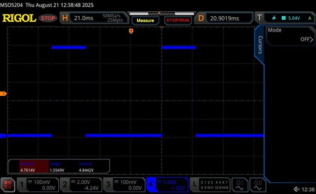
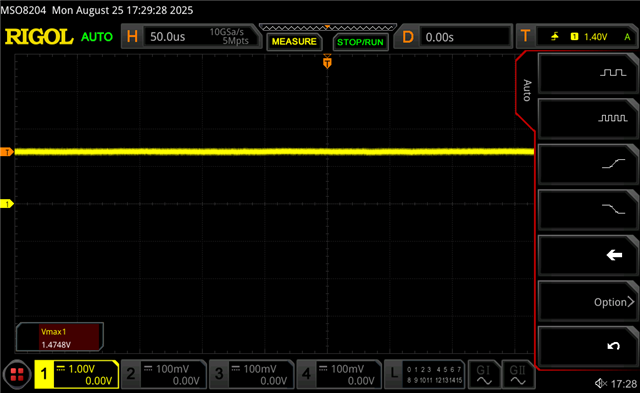
In the HD3SS3220IRNHT, we've connected the ID pin to 1.8V using a 200kΩ pull-up resistor. However, when the USB port is set to UFP (Upstream Facing Port) mode, the ID pin voltage drops to around 295 mV, rather than staying near 1.8V. When we reduce the pull-up resistor to 100kΩ, the voltage increases to about 400 mV, but it's still much lower than expected. Is this the expected behavior. We are monitoring the ID pin to detect Device attachment, as the voltage level is low, there is a possibility that it might be wrongly interpreted as Device attachment. Is there a recommended pull-up resistor value for 1.8V supply?

Thanks & Regards,

Sneha

  • Hi Sneha,

    We recommend pulling the ID pin up to VDD/5V with a 200KOhm resistor.

    For a UFP application, we recommend using the VBUS_DET pin for device attachment rather than the ID pin. The ID pin should only be pulled low when a connection is detected while set as a DFP or configured as a source in DRP. In a UFP setup, the VBUS_DET pin is used to determine when a connection has been made with a DFP host, monitoring VBUS from the DFP as part of the CC negotiation process.

    Please let me know if you have any other questions.

    Thanks,

    Ryan

  • Hi Ryan,

    Could you confirm the minimum pull-up resistance required for the ID pin?

    Also, it is an open-drain output, can't we pull it up to 1.8V, would this works fine.

    Thanks,

    Sneha

  • Hi Sneha,

    We recommend 200KOhm, a lower value can be used though:

    Also, it is an open-drain output, can't we pull it up to 1.8V, would this works fine.

    Yes, that would work fine with you are using something that reads 1.8V as high, I don't see any issues with that.

    Again, for a UFP application, it is better to use VBUS_DET for detecting VBUS, as opposed to the ID pin, which has no functionality when set as a UFP.

    Thanks,

    Ryan

  • Thanks Ryan,

    We are interested to know the functioning of the ID pin for the DFP mode. In our system we have a load switch to enable power to the peripheral(ex : mouse, pen drive), the enable of the switch in driven from the controller based on the ID pin status. When we measure the voltage of the ID pin it is always below 0.4V(in both UFP and DFP mode) , because of which we are not able to differentiate between UFP and DFP(datasheet says in DFP mode ID pin goes low, hence we are monitoring for logic Low at the controller, but even in UFP the ID pin is interpreted as logic Low because of the voltage level). Can you suggest what changes can be done in order to achieve this?

    Our requirement is as follows

    1. When our board is device(UFP), ID pin should stay high and the external device provides power to our board

    2. When our board is host(DFP), ID pin should go low based on which we enable the load switch to provide power to the attached peripheral like mouse, pen drive etc.

    The load switch should not be enabled in case 1 as it becomes multi driven. It should get enabled only when ID pin goes low

  • Hi Sneha,

    1. When our board is device(UFP), ID pin should stay high and the external device provides power to our board

    2. When our board is host(DFP), ID pin should go low based on which we enable the load switch to provide power to the attached peripheral like mouse, pen drive etc.

    The load switch should not be enabled in case 1 as it becomes multi driven. It should get enabled only when ID pin goes low

    This makes sense, and the HD3SS3220 should be able to support this.

    When set as a UFP, the ID pin should be high at all times, regardless of whether there is a connection or not.

    When set as a DFP, the ID pin will be high when there is no connection. Then, once there is a connection to a UFP device, the ID pin will be pulled low to indicate that VBUS should be sent.

    When there is no connection, is the ID pin high? Or is it still pulled-down to that .4V range? Are you using I2C mode, or manually setting the device as UFP/DFP/DRP?

    Would it be possible for you to send the schematic over for me to review?

    Thanks,

    Ryan

  • Hi Ryan,

    Attached the schematics for your review. 

    Even when there is no connection, the ID pin is pulled down to 0.4V. We have floated the PORT pin in the design to enable DRP mode. We are not using I2C to set the device mode. 

    USB_Connector_TI_Forum.pdf

  • Hi Sneha,

    If you set the HD3SS3220 to specifically DFP mode, does that change anything? I would like to see if changing out of DRP to specifically one of the other modes has any effect.

    Are you able to try a different voltage for pulling up ID? Again, I believe it should still work with 1.8V, but I would like to see if it has any effect.

    Do you have any way to enter and use I2C, or is it strictly GPIO mode?

    What is the voltage on the CC pins?

    Thanks,

    Ryan

  • Hi Ryan,

    We do not have an option to change the pull up voltage as this is going to SOM which is of 1.8V IO logic.

    Also currently I2C is not established hence we are unable to test this as well.

    I have attached the CC pin voltage waveform when the cable is left unconnected at the other end. We are seeing a pulsed waveform varying between 0V to 5V.

    Can we change the pull up resistor on the ID pin to 10K, is it strictly recommended to use 200K, does lowering the resistor value cause any issue for the device working?

  • Hi Sneha,

    It looks like the CC pins are properly toggling for DRP, so I don't see any issues there. If possible, I'd like to see the voltage on these pins when there is a connection to see the status then. If you could also capture VBUS and the ID pin, that would also help for getting a deeper understanding.

    Can we change the pull up resistor on the ID pin to 10K, is it strictly recommended to use 200K, does lowering the resistor value cause any issue for the device working?

    The ID pin is an open-drain output, so 10Kohm's should be fine. We recommend 200K because a 10KOhm resistor may cause issues with pulling the signal down to a low-enough voltage when a DFP connection is detected.

    Thanks,

    Ryan

  • Hi Ryan,

    We tested the ID pin with a 10 kΩ pull-up to the 1.8 V I/O logic of the SOM and in this case, the status is read as HIGH.

    The observed results with the 10 kΩ pull-up are as follows:

    1. DFP mode: When the system is connected to a peripheral (ex: mouse), the ID pin reads LOW at 84 mV I/O logic.

    2. UFP mode: When the system is connected to a host (laptop), the ID pin reads HIGH at 1.47 V I/O logic.

    Could you confirm if changing the pull-up resistor from 200 kΩ to 10 kΩ is acceptable. I have also attached the waveform captured in UFP mode for reference.

  • Hi Sneha,

    The observed results with the 10 kΩ pull-up are as follows:

    1. DFP mode: When the system is connected to a peripheral (ex: mouse), the ID pin reads LOW at 84 mV I/O logic.

    2. UFP mode: When the system is connected to a host (laptop), the ID pin reads HIGH at 1.47 V I/O logic.

    It looks like the ID pin is acting as expected. You aren't seeing any issue in the USB3 SS connection correct, the connection looks as expected?

    Could you confirm if changing the pull-up resistor from 200 kΩ to 10 kΩ is acceptable. I have also attached the waveform captured in UFP mode for reference.

    If the ID pin is operating as expected with a 10KOhm pull-up, then there isn't any problem with using a 10KOhm resistor. 

    Thanks,

    Ryan

  • Thanks Ryan,

    We are currently testing in High-Speed mode and haven’t observed any issues.

    Could this configuration potentially cause any problems in SuperSpeed mode?

    Regards,

    Sneha

  • Hi Sneha,

    This should not cause any issues in SS mode.