This thread has been locked.

If you have a related question, please click the "Ask a related question" button in the top right corner. The newly created question will be automatically linked to this question.

UCC28056: Need suggestions to improve the PFC of the IC.

Part Number: UCC28056

Tool/software:

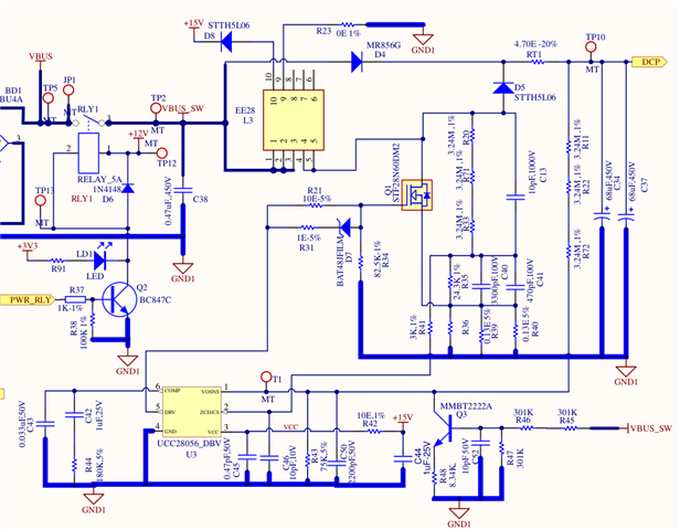
I am trying to use UCC28056B for my project, which requires the usage of an Active PFC component to drive a DC Motor.

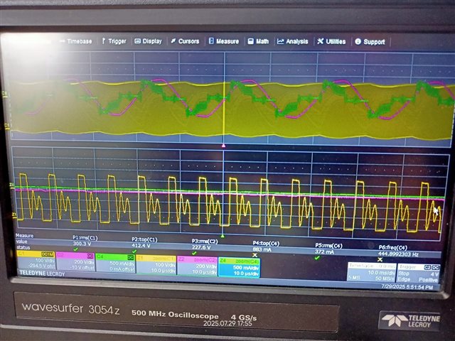
1. This is the Switch Load Voltage (Yellow)  and Inductor Current Waveform(Green) that I am getting.

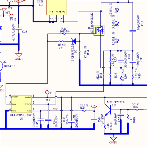
2. Currently using Inductance of value 220 µH.

3. Switch Load Voltage and Inductor Current are slightly going below zero, need some guidance for this too.

4. I am willing to provide additional info if required.

5. Current sensing resistor is Rcs=75mΩ

  • Hi,

    Can you please clarify what is the issue here? Current goes below zero?

    By principle, the current cannot be negative. Please share the schematic and your setup illustration for investigation.

  • This is a Portion of my Schematic. R39 and R40 are the Current Sensing Resistors.

  • The schematic looks very close to the EVM. Are you asking why the current is negative?

    How do you measure the current and where do you prove?

  • Measured current by using current probe on the inductor (green waveform). for the yellow waveform, I measured across C46 capacitor to check ZCD/CS pin.

    Yes, schematic is based on UCC28056 EVM for the active PFC part. Trying to tune parameters.

  • Hello Ananyo, 

    What is the output power target of your PFC design?

    Your choice for MOSFET may be too big; this device has close to 10000pF when it is on. 
    That Coss is ringing with your boost inductor and generating the negative resonant current.   

    Negative resonant current is normal, but its amplitude depends in part on Coss.  
    In your waveform the neg current is a significant potion of the overall inductor current. 
    It shows -100mA peak vs. +370mA peak, so this distorts the Ac line waveform and reduces PF.

    If the current shown is at maximum power, try using a much smaller MOSFET. 

    Regards,
    Ulrich

  • The required output power target is 165W. The current shown during testing is for much lower power, around 95W and 85W (Different power because of running the motor at different RPMs). I have attached additional Images from Scope during testing. (Left: 95W, Right: 85W).

    We were using HCS80R850S MOSFET.


  • Details of the MOSFET used:

    HCS80R850S- TO-220F Package 800V 6.6A 0.85Ω 

  • Please give us few days to get back to you.

  • Hello Ananyo, 

    I think your input capacitance (Cin) may be too high in value.  Is C38 the only Cin you have or is there more not shown in the schematic portion above?
    Please provide your complete PFC schematic.  

    Try reducing C38 to 0.1uF to see the effect on the AC current waveform. 

    Regards,
    Ulrich

  • Hello Ulrich,

    Cin (C38) is the only input capacitor.

    Some of the resistor values have been modified in the design under testing, as follows:

    R33, R71 ,R20: 3M Each (Upper current sensing resistors)

    R72, R22, R11: 3M Each (Upper voltage sensing resistors)

    R43: 58k ohms ((Lower voltage sensing resistor)

    C45: 0.47 uF

    Details of the MOSFET used:

    U1: HCS80R850S- TO-220F Package 800V 6.6A 0.85Ω 

    Can you elaborate on what effect reducing Cin (C38) will have on the AC current waveform.

    Please do mention any more details you may need from my side. 

    Regards,

    Ananyo

  • Hello Ananyo,

    The purpose of Cin (C38) is to be a local bypass filter for differential-mode switching current. 

    At light loads, a side-effect of this capacitor is that it stores charge and can keep a voltage that is higher than the AC line voltage when the line is near the zero-crossing.  Any light-load inductor current is pulled from the stored charge of Cin, rather than coming in from the line through the diode bridge.   

    So, when Cin is providing the inductor current, the input current is 0 and you see flat 0A segments in the AC current waveform.
    A lower value for Cin stores less charge and the light-load 0A segments will be smaller. 

    Thank you for the expanded schematic.  It shows that the inductor has an auxiliary winding for +15V bias.
    What is the polarity of the windings?  I assume it is like a flyback arrangement, but please verify. 
    How much power is being drawn from this winding?  
    This may account for some of the additional distortion other than the flat spots.   

    What is the purpose of the Q3 circuit on VOSNS?  
    Any amount of collector current will make the PFC output voltage (DCP) go up. 

    Regards,
    Ulrich

  • Q3 and the corresponding circuit on the right side of it (R46, R48, C52 etc) are not being used currently; they can be ignored.

    Also, the Diode D8 (+15 V) is not populated currently, hence it can also be ignored.

  • Hello Ananyo,

    Thank you explaining about Q3 and D8.  If there are any other components shown in the schematic diagram that are not actually populated, please let me know. 

    Have you tried reducing the value of C38 as I suggested ~6 days ago?  
    If so, has there been any improvement in the THDi?  

    Regards,
    Ulrich