This thread has been locked.

If you have a related question, please click the "Ask a related question" button in the top right corner. The newly created question will be automatically linked to this question.

LM61495: The IC doesn't survive a short circuit on its output

Part Number: LM61495

Tool/software:

Hello,

We are using a LM61495 to convert an input from 24-36 V to 22 V. We have based our circuit on a webench generated one, although we set it to a 24 V output, later changed to 22 V by setting Rfbb to 4700 Ω to have some voltage difference. Link to the circuit. The output is only used to power three half bridges with a driver.

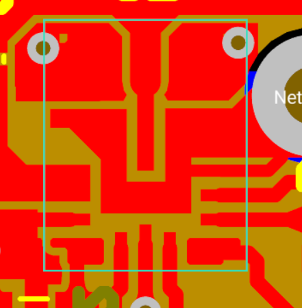
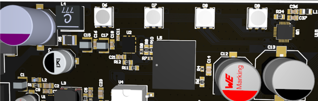
Our design is as follows (R6 changed to 4k7):

The output is working fine, the voltage is correct, and it can work up to 10 A without heating up too much.

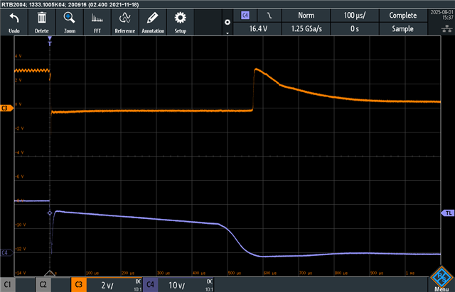
The problem we are having is that, when shorting the output, the IC gets damaged, and the Vin and SW pins short to ground. We have a half bridge on the output, and the test consists of activating the high side while the output is shorted to ground. The half bride driver has overcurrent protection, but it seems like the IC gets damaged before it activates. It fails both at 22 V and 11 V output.

We have tested with the evaluation module LM61495RPHEVM wired to the board. The input connected to C19 with wires, and the output at C12 with more wires, and with the IC removed. The output from the board was changed to 22 V by replacing the RFBB5V with a 5k6 resistor. In that case, the buck survives the short, and the overcurrent protection of the bridge driver is triggered. It has survived multiple tests.

We don't know what may be the difference that allows the evaluation module to survive, while the IC on board fails. We were thinking that it may be either the output capacitance, the inductor value, or the input filter. Do you have any tips on what may fail, and what should we measure to see it? And what we should change on our design to survive?

  • Hi Daniel, 

    It seems that I am unable to open it; is there any way it can be shared in a different format? 

    Additionally, if you can, it would be helpful to see the layout files as well. This can also play a role in the device's ability to survive this test.

    Thank you,

    Joshua Austria

  • I think the way I attached the link broke. Here it is: https://webench.ti.com/appinfo/webench/scripts/SDP.cgi?ID=093F2CE60FC05394

    For the layout, I'd rather sent it to you in private, as it is confidential. But I have noticed that the connection of the PGND pins to the board ground is done by two 0,3 mm vias, one per pin. Do you think that this may be what is causing the problems?

  • I have soldered wires from the PGND pads to ground, and now it survives when the output is short-circuited while set at 11 V. It seems that the poor connection to ground was the issue. It still doesn't survive when set at 22 V and shorted, but it might be that the wires are too long.

    Here is a screenshot of a test when the output is at 22 V, in blue, and the driver fault signal in orange. Although the driver stops the short, after the output is restored partially, the voltage goes down, and the input gets shorted. But I guess it's just that the connection to ground still isn't good enough.

  • Hello,

    The responsible engineer is out of office and will reply next week.

    Best regards,

    Ridge

  • Hi Daniel,

    Yes, that looks to be the case. Wires like those placed during your test, can help but those also introduce extra inductances and are not as good as using a wide top side ground plane. 

    Our recommendation would be to emulate the EVM for this device for layout. As you have tested this already, we are confident that this should be a good layout for your use case with this device.

    Thank you,

    Joshua Austria