This thread has been locked.

If you have a related question, please click the "Ask a related question" button in the top right corner. The newly created question will be automatically linked to this question.

LM3409HV: Component failure at power-on / start-up

Part Number: LM3409HV
Other Parts Discussed in Thread: LM3409,

Tool/software:

I am working on a design for an LED Driver using the LM3409HV. The input voltage is 48V and the board is required to drive different LED strings from 3.5A, to 4.5A maximum. A schematic and bill of materials for our design is included. We are using analog dimming which will be derived from an off-board analog signal - the board will plug into a motherboard which will hold several of the driver boards. The initial testing has been done with the board stand-alone using a trim-pot on the board for the analog dim signal. We have worked with 2 different p-MOSFETs. Gate charges for the 2 MOSFETs are 27nC and 41nC. We have had issues with the LM3409 blowing up. When this occurs, the MOSFET is also shorted. At failure, the MOSFET is shorted, the LED string is full-on, and drawing max current. The sense resistor appears to be undamaged. The failure occurs at power on with the enable signal asserted or not. (A pull-down on the EN pin is installed on the board.) When the board is working, we had no issues running the board, powering a 4A LED string with either MOSFET. We have airflow over the board which is fabricated with 2oz copper. We have done thermal measurements and have not seen thermal issues with any of the board components. I have not seen any transients on the output at start-up or at steady state. We added a schottky diode to the board from the output to the 48V and we still have failures. (found post on TI support forum) Do you have any suggestions? Is there possibly a 48V rise-time issue, or 48V, 12V sequencing issue? I also found this post on the TI support forum (posted about 30 days ago): LM3409HV: LED maximum current. The answer from the support engineer is that the LM3409HV is not recommended for drivers >4A. The LM3409HV datasheet notes in the description on page 1 that it can 'easily drive >5A'. Is the LM3409HV not a good fit for our application? Some other questions: - We do not have all the LED strings for our project as of yet, is it ok to test with resistive loads? - Can multiple LM3409HV circuits be paralleled to drive the higher currents? (Again, the LED max current post suggests another TI part for paralleling the outputs.) Thank you for your help. Robert D.

LED_DRIVER_BOARD_SCHEMATIC_REV-.pdfLEDDriverBOM.xlsx

  • Hello Robert,

    • What is the number of LEDs and the Vf at the output current setpoint?  Do you have a range in the number of LEDs? 
    • I noticed you are using a 3A diode, that doesn't seem correct given an operating current of 4-5A.  I don't know what the Vled range so I can't calculate the duty cycle of the switcher and the rms currents through the diode.
    • It can support 5A operation but that depends on the input and output conditions along with components used.  The P-channel FET driver doesn't have a strong gate driver, 2 ohms source, and 2 ohms sink.  That means depending on the fet used (ones with large gate charge) it might have a hard time to drive it quickly and turn on the FET fully before the blanking period.  That shouldn't make it damaged but it might give you much smaller currents or inconsistent operation.  
    • Did you capture waveforms of the failure event?  It would be nice to see the inductor current, the SW node, Vled, and p-fet gate drive.  Maybe look at COFF signal too, to make sure you reach the off time.  We need to figure out now it get damaged and why before we can address how to fix it.  It this something that is fairly repeatable?  
    • How are the supplies controlled?  Is 48V applied first or 12V?  It would be good to have power up signals of 12V and 48V rail
    • Are you shunt fet dimming using Q2? What is PWM frequency and duty cycle range?  You schematic seems to have this as a no load.  How are you controlling the dimming?  PWM?  Analog (IADJ)?    
    • Resistive load is ok, but using the actual LED is better.  LEDs are dynamic impedances, unlike resistors.  
    • Yes,you can parallel current sources to get high currents.  

    I really think you need to try and capture the even of when it gets damaged.  Try and use all the signals on your scope to see what is happening.  SW node, inductor current, Vled, and some other signal like gate drive, Coeff, etc.  This a very simple device and usually you can figure out what is going on once you get those waveforms during the failure event. 

     -fhoude


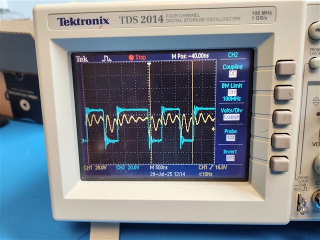
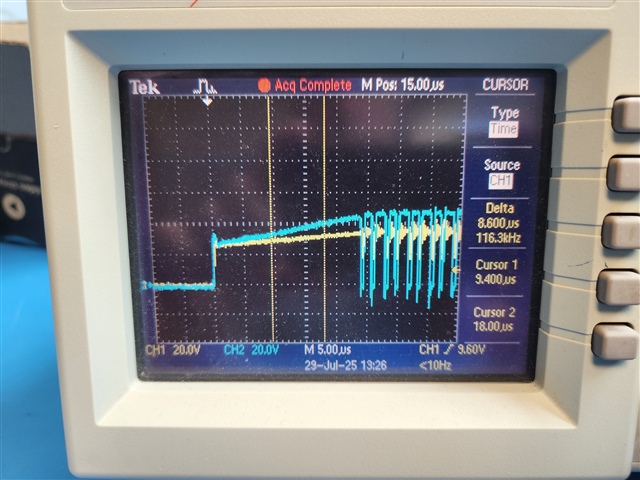
  • Failure occurs infrequently and I have not yet been able to catch any scope waveforms when the failure occurs. I have attached 2 waveforms: one during steady state operation (wfm1) at 2.5A and another at 4A at startup (wfm4). At startup the 48V and 12V are on, then the scope is triggered as the waveforms rise from an enable assertion. Yellow = LED volts out, cyan = D1,L1,Q1 node.

    I do not have information on the number of LEDs in the string we are using from our customer. At the 4A drive current the voltage is 31V (max 35V).

    On our test bench, the 48V and 12V are from separate supplies and are turned on manually. In the actual application, 48V will come up first, the 12V is derived from the 48V.

    The board only has the analog dimming circuitry installed. The PWM dimming circuit is not populated. We intend to use analog dimming only in our application. For testing the board is currently using the pot to set the IADJ pin.

    Robert D.

  • Hello Robert,

    You need to look at all the nodes and currents I told you to look at during the power up cycling and trying to find the event that might be causing the damage.   You have 4 channel scope, please use all of them to get as much information as you can when the startup happens, see my comments before about what might be good node to monitor.  I hope you have a current probe, it would be useful to see the inductor current.   

    I noticed you enable the EN pin at like ~4V, isn't there any reason you are doing that.  I would adjust that such that it used as UVLO for the enable tied to 12V.  

    Do you have your design calculations for the component values you have selected?  I could review them.  

    -fhoude

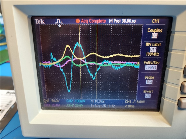
  • Attached are 2 scope traces at start-up. (yel=48V VIN, blue=LEDOUT current 100mV=1A, magenta=12V, green=LEDOUT volts)

    Wfm6 shows that the VIN from our bench supply at start-up is unstable and spikes up to 100V (which is over the 75V max LM3409HV rating). Please comment and confirm that this is likely our issue. The board did not fail, but given the waveforms, I did not continue with this power supply. This test was done with the enable pin being held low at start.

    Wfm12 is a start-up using a different power supply. The 48V DC supply is powered on with the enable asserted and the IADJ set for 4.25A. The 48V DC supply is a stable ramp up at start and the LM3409 output appears to perform as expected. Please comment.

    We also intend to connect two of the LM3409HV board designs in parallel to one light strip setting the current for each board to 3.75A. You mentioned in a previous post response that the boards can be paralleled. Please confirm and comment.

    Thank you,
    Robert D.

    wfm6_12.zip

  • Yes, this is very much likely why.  You might need to increase input capacitance or put a TVS/Zener to clamp the voltage.  I am surprised as how large the overshoot.  What is providing the 48V rail?  Is it designed to handle the load transients seen by the LED driver?  Now you know why you are blowing up the LM3409 and the P-FET not you need to figure out how to prevent it.  If you need help let me know.  

    -fhoude