This thread has been locked.

If you have a related question, please click the "Ask a related question" button in the top right corner. The newly created question will be automatically linked to this question.

TPS25946: TPS25946 – Controlled battery hot-plug with balancing between 2 LiPo 2S packs

Part Number: TPS25946
Other Parts Discussed in Thread: BQ25756E, , TPS25948, BQ25756

Tool/software:

Hello,

I'm looking for a reliable solution to connect two LiPo 2S 7500 mAh packs in parallel, each with its own integrated BMS, in a system that uses a single TPS25730S + BQ25756E charger, charging at 3.75 A (0.5 C).

In certain situations, a second identical pack may be hot-plugged to extend runtime.
However, the end-user has no way to manually balance the two batteries before connecting them, which may lead to a voltage difference of several hundred millivolts. Once connected and balanced, both packs need to be charged.

Solutions considered:

  1. Direct parallel connection, but too risky due to potentially high balancing currents between the packs.
  2. Controlled balancing circuit prior to connection
    • Measure ΔV between the two packs;
    • If ΔV > 100 mV, activate a current-limited balancing path;
    • Once voltages are close enough (ΔV < threshold), connect the second pack via a TPS25946.
  3. Bidirectional converter between the two batteries, before connecting them in parallel. Technically interesting active solution, but too bulky for my PCB constraints.
  4. Connect battery 2 to the input of the charger. Feasible, but battery 2 wouldn’t be charged unless a second charge path is added after battery 1, which would overly complicate the architecture compared to solution 2.

Current architecture under consideration:

A controlled passive balancing step before making the parallel connection, although I'm a bit concerned about the efficiency of this approach.

In this setup:

  • As long as the packs are not balanced, the battery 2 TPS switch stays OFF. (Charging is blocked but it's acceptable);
  • The TPS of battery 1 mainly acts as inrush limiter and provides UV/OV/OC protections.

I also considered an alternative where the more charged battery powers the system alone, until the voltages get close enough to safely connect both in parallel.


This would avoid passive balancing, but seems more complex to implement, especially during the transition phases.

I am seeking your technical feedback on the feasibility of these approaches, any experience or insights you may have from dealing with similar challenges, and suggestions for TI components if you believe my current choices could be improved.

I'm also wondering whether I'm overcomplicating the problem and if a simpler solution would be sufficient.

I haven’t finalized the schematic for this section yet, I’m still exploring viable architectures and suitable components.

I have already started working with the TPS25946 and have a question regarding the diode and resistor placed in parallel between the OUT and IN pins. I believe I understand their purpose, to enable the circuit during reverse conditions (e.g. during charging in my case). However, since the circuit is always powered by the battery in my setup, I’m wondering if these components serve any other function or protection, or if they can be omitted?

Thanks in advance for your help.

Valentin.

  • Hi Valentin,

    I have already started working with the TPS25946 and have a question regarding the diode and resistor placed in parallel between the OUT and IN pins. I believe I understand their purpose, to enable the circuit during reverse conditions (e.g. during charging in my case). However, since the circuit is always powered by the battery in my setup, I’m wondering if these components serve any other function or protection, or if they can be omitted?

    These resistor and diode are placed in this example to allow current to flow when device is off and eventually turn on the eFuse (Vin > 2.7V) so that device's internal path can allow current flow. This device do not provide bi-directional path when off so we require this system workaround. In your setup, it is always on so these are not required. They do not have any role in other functionality or protection. They can be omitted.

    Regarding your other question on the system architecture you are considering. Let me check that and get back to you.

    Best Regards,
    Arush

  • Hi Valentin,

    I was discussing this with my colleague, and we came up with a better solution.

    parallel.

    My proposal is to use similar type of architecture i.e. no need to use current-limited battery balancing path but instead use TPS25948 instead of TPS25946. 

    When you need to charge the battery, disable to RCB of TPS25948 to allow charging. When discharging, enable to RCB of eFuse. This will ensure that only one battery is connected whichever has higher voltage until both automatically balances due to system load and then both will turn on together. 

    Can you tell me your end application? If it is automotive then I won't recommend TPS25948 due to its wcsp package. 

    Best Regards,
    Arush

  • Hi Arush,

    Thank you for the detailed suggestion.

    Your approach using the TPS25948 is much more elegant than what I initially considered, and I appreciate the clarification regarding the RCB pin behavior. This is a non-automotive project, so the WCSP package is ok.

    I've started adapting my schematic with this part. The behavior during discharge is clear, and your proposed solution fits that use case.

    However, I'm still evaluating the best way to control the RCB pin during charging. I’m currently exploring a few options, and I’d appreciate your thoughts.

    One idea is to use the PG pin of the BQ25756E charger to drive RCB. However, as shown in Figure 9-3 of the datasheet, there’s a ~180 ms delay between cable insertion and the actual start of charging.
    I'm not sure whether this delay is acceptable if the voltage difference between the two batteries is significant.
     I’m concerned that the TPS eFuse might trigger a fault due to high balancing current during that time window.

    Another option I’m considering is to rely on the STAT1/STAT2 logic of the charger. If I detect STAT1 = High and STAT2 = Low, I could use that as an indicator to deassert RCB and allow balancing.
    But I'm unsure whether the charger will enter “charging” state if RCB is asserted on both battery inputs. Does the BQ25756E require current to flow before those status signals become valid? Or would the charger correctly detect and report “charging in progress” even if RCB is still blocking reverse current at startup?

    Thanks again for your support and time, I feel this architecture is close to being fully functional, and I just want to ensure the final behavior is robust.

    Best regards,
    Valentin.

  • Hi Valentin,

    One idea is to use the PG pin of the BQ25756E charger to drive RCB. However, as shown in Figure 9-3 of the datasheet, there’s a ~180 ms delay between cable insertion and the actual start of charging.
    I'm not sure whether this delay is acceptable if the voltage difference between the two batteries is significant.
     I’m concerned that the TPS eFuse might trigger a fault due to high balancing current during that time window.

    I checked the BQ device datasheet and it looks like this will indeed be an issue.

    Another option I’m considering is to rely on the STAT1/STAT2 logic of the charger. If I detect STAT1 = High and STAT2 = Low, I could use that as an indicator to deassert RCB and allow balancing.
    But I'm unsure whether the charger will enter “charging” state if RCB is asserted on both battery inputs. Does the BQ25756E require current to flow before those status signals become valid? Or would the charger correctly detect and report “charging in progress” even if RCB is still blocking reverse current at startup?

    Let me add my colleague who supports this BQ device. He is expert on this device.

    Also, if you consider using sequential charging and detect STAT pins for charging in progress and charging done states and control RCB1 and RCB2 pins. 

    Best Regards,
    Arush

  • Hi Arush,

    Thanks for looping me in!

    Valentin,

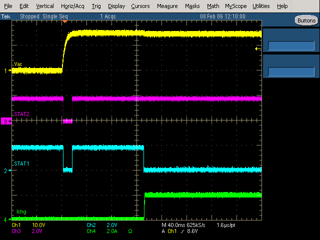
    I don't completely understand the timing of what needs to happen specifically with the BQ25756E. I have just captured these screenshots of the STAT1, STAT2, and /PG pins from the BQ25756 on our EVM:


    It is important to note here that the current isn't the necessary condition for STAT1 to be low and STAT2 to be high, rather, it's switching of the converter.

    If the charging process needs to be perfectly lined up with our digital pins, I think using STAT1 and STAT2 will work. STAT1 high and STAT2 low means charging has completed, however.

    Do these screenshots answer your question?

    Best regards,
    Michael