Tool/software:
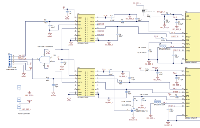
If The sub-board LMG3410-HB-EVM only connects to a 5V auxiliary power supply. There are signals on the gates of Q1 and Q2. Pin 13 of U1 is 0V, and pin 14 is 5V. Both pins 13 and 14 on the lower arm are 5V, and the Vgs is also 5V.
If a duty = 0 switching signal is connected, the gate voltages of Q1 and Q2 can be reduced to 0. At this time, pins 13 and 14 of U1 are both at 1.5V, pin 13 of U2 is 0V, and pin 14 is 5V, so Vgs = 0V. If an input voltage (AC source) is applied to the motherboard, the current will be very small, occurring only in the positive half cycle.