This thread has been locked.

If you have a related question, please click the "Ask a related question" button in the top right corner. The newly created question will be automatically linked to this question.

TPS54260-Q1: Vin equals to Vout

Part Number: TPS54260-Q1

Tool/software:

Hello team,

I have designed output voltage for 5V with feedback resistor and output current is 150mA to 400mA.

I have kept the EN pin floating to turn on the device even with lower voltage.

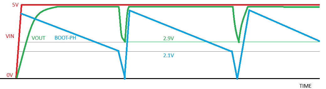
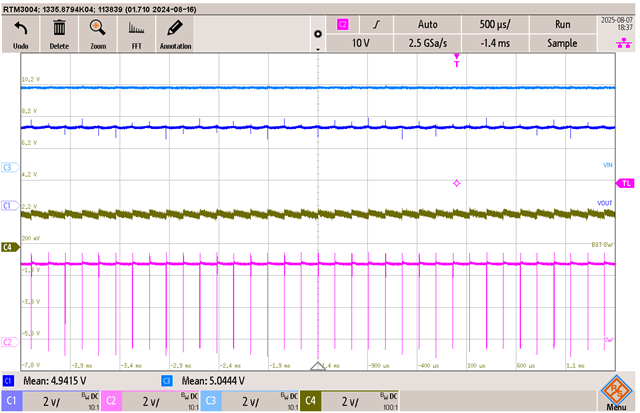
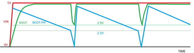
Let's say I apply 5V input for long period, the output voltage will also be nearly 5V as the device operate in 100% duty until BOOT - PH drops below 2.1 V.

1. Can we determine the rate of discharge of the BOOT capacitor to determine how long the 5V remains constant until the BOOT - PH drops below 2.1 V?

2. When BOOT - PH falls to 2.1V, the MOSFET will turn off and output capacitor starts discharging and when it is 5V-2.1V=2.9V the BOOT -PH rises and output rises 5V so BOOT - PH also rises nearly to 5V. This keeps repeating right if input voltage is constant at 5V. Is my understanding correct? (see graph below and correct if I am wrong)

Thank you,

  • Hello Vishwas

     Can we determine the rate of discharge of the BOOT capacitor to determine how long the 5V remains constant until the BOOT - PH drops below 2.1 V?

    Yes Vishwas, you can determine it experimentally.

    When BOOT - PH falls to 2.1V, the MOSFET will turn off and output capacitor starts discharging and when it is 5V-2.1V=2.9V the BOOT -PH rises and output rises 5V so BOOT - PH also rises nearly to 5V. This keeps repeating right if input voltage is constant at 5V. Is my understanding correct? (see graph below and correct if I am wrong)

    When Boot uvlo triggers, device turns off the top FET and BST cap start charging through inductor current, but Vout has to fall below a level such that BST cap charges above BST UVLO rising threshold. This problem is particularly evident at lighter loads as there not enough inductor current to charge BST cap during normal operation. Every cycle BST cap discharges more while turning on the TOP FET than it charges during off period. Thus, it ultimately hits the UVLO.

    Thank you

    Regards

    Onkar Bhakare 

  • Hello Onkar,

    For the second point, I understand Vout should fall below such that BST cap charges above the BST UVLO rising voltage.

    Let's say output current is 150mA to 400mA. Then does the output voltage fall to 2.9V (5V-2.1V) like the graph below?

    Could you please share the data how the output voltage behaves when output is set to 5V and input of 5V is applied? 

    Also, can i know light load means how much current?

    Thank you,

  • Hi Vishwas


    Could you please share the data how the output voltage behaves when output is set to 5V and input of 5V is applied? 

    We do not have data for 5Vout and 5Vin. However, behavior would be similar at slightly higher Vin, you can refer following app note. It discussed about similar behavior you are referring to Methods to Improve Low Dropout Operation with the TPS54240 and TPS54260 (Rev. A)

    Thank you

    Regards

    Onkar Bhakare

  • Hello Onkar,

    The app note discuss more during light load condition (DCM). During CCM (inductor current not zero) the inductor current will pull the PH Pin to GND when the MOSFET is OFF so that bootstrap capacitor will charge and Vout will be always equal to Vin right during CCM mode?

    Thank you,

  • Hello Vishwas

    Yes, you're understanding is correct. During Continuous Conduction Mode (CCM), you won't experience this issue. With 5V Vin, there's sufficient voltage to charge the bootstrap capacitor when the inductor current pulls the SW node low during off-time. Additionally, the bootstrap capacitor gets refreshed at the switching frequency rate

    This becomes problematic especially during ECO-mode operation, where the switching frequency significantly reduces depending on the load condition. In CCM, since the inductor current never reaches zero, the SW node is consistently pulled low during SW off-time, ensuring regular bootstrap capacitor charging.

    Thank you

    Regards

    Onkar Bhakare  

  • Hello Onkar,

    How can the bootstrap capacitor refresh at switching frequency rate when Vin is equal to Vout and working in CCM mode because when Vin is equal to Vout it works as 100% duty cycle and switch ON time will be more?

    Thank you,

  • Hello Vishwas,

    The case I was discussing earlier refers to when the device is operating at its set frequency. As you correctly pointed out, in dropout operation, the high-side FET will only turn off when the bootstrap UVLO triggers. Once BST UVLO triggers, the device turns off the HS FET, and the inductor current pulls the SW node low, which recharges the bootstrap capacitor.

    Let's analyze the minimum current case in your application (140mA):

    Energy required to charge the BST cap by 1V:

    • Assuming a 100nF BST cap
    • Ebst = 1/2 × C × V² = 50 nJ

    Energy stored in the 33μH inductor:

    • 1/2 × L × I² = 1/2 × 33μH × (140mA)² = 323 nJ

    However, it's important to note that this stored energy in the inductor also has to supply the load, so not all of it is available to charge the BST cap.

    Now let's calculate how long the inductor has to support the load before the top FET turns on again:

    • To charge BST cap by 1V, required time can be calculated as:
    • dt = C * dV/I
    • dt = 100nF * 1/0.14A = 715ns

    Energy supplied to load during this duration would be:

    • = Vout * Iout * dt
    • = 5 * 0.14 * 715ns
    • = 500nJ


    Based on these calculations, the available energy may not be sufficient to fully recharge the bootstrap capacitor. Thus, It looks inductor current would become discontinuous, before BST cap can charge enough. 

    I'll verify this behavior on our EVM at 5V input and get back to you with test results by Friday.

    Thank you

    Regards

    Onkar Bhakare

  • Hello Onkar,

    Sure, let me know the result (hope the inductor 33uH is sufficient to maintain 140mA in CCM mode when Vin is much greater than Vout).

    Also, BST cap should charge by at least 2.1V right not 1V you mentioned?

    Thank you,

  • Hi Vishwas

    Also, BST cap should charge by at least 2.1V right not 1V you mentioned?

    1V I mentioned is on top of 2.1V. When BST UVLO hits, level would be 2.1V but to have bare minimum margin over UVLO, I took del_I = 1V.

    I'll test this on EVM. Meanwhile I recommend you simulate it on Pspice for TI. 

    Thank you

    Regards

    Onkar Bhakare

  • Hello Vishwas


    I tested this behavior on EVM,  

    Check the following waveforms.

    Vin = 5.28V, Vo = 5.20V, Io = 140mA

    Vin = 5.27V, Vo = 4.6V, Io = 140mA

    Vin = 5V, Vo = 4.26V, Io = 140mA

    On EVM, it needs at least 170mA current to come out of this behavior

    VIN = 5V, Vout = 5V 

    The simple solution would be to have dummy load of 50-100mA, assuming your application allows it. Or you can tie a diode from Vout to BST pin as mentioned in Methods to Improve Low Dropout Operation with the TPS54240 and TPS54260 (Rev. A).

    Hope this helps

    Thank you

    Regards

    Onkar Bhakare 

  • Hello Onkar,

    Thanks for the quick response and insights.

    Regards,

    Vishwas H R

  • Thanks Vishwas

    Glad it helped!