This thread has been locked.

If you have a related question, please click the "Ask a related question" button in the top right corner. The newly created question will be automatically linked to this question.

TPS51215A: SCHEMATIC CHECK

Part Number: TPS51215A

Tool/software:

Hi

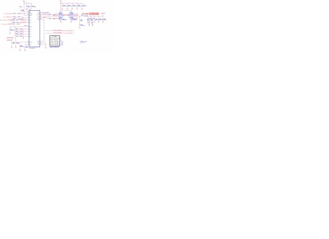
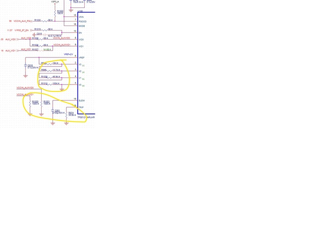
Could you help check the below TPS51215A schematic and any need to adjust 

The inductor was 0.22uH with a DCR of 0.63mohm and was replaced with a 0.22uH with a DCR of 0.29mohm.

The inductor DRC is different. Does the resistance in the yellow circle on the circuit need to be fine-tuned? 

Thanks

  •    

    The graphics you inserted into the post do not have high enough resolution to be readable for a schematic review.

    The inductor was 0.22uH with a DCR of 0.63mohm and was replaced with a 0.22uH with a DCR of 0.29mohm.

    The inductor DRC is different. Does the resistance in the yellow circle on the circuit need to be fine-tuned? 


    If they had a working design using a 220nH, 0.62mΩ Inductor, and it was replaced with a 220nH 0.29mΩ inductor, the change in the inductor's DCR would not require a change to the design.

    If you need more review than that, we'll need higher resolution schematic images to review.