


Tool/software:
Hi TI Expert,
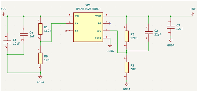
I'm having issues with my component. I believe I interpreted the documentation incorrectly and I wanted to double check. My input voltage is 14.4V and I was using a 110K resistor to a 10K resistor for my voltage division. This resulted in a voltage of 1.2V to the Enable pin. I now realize 1.2V is the minimum value for enable high and my enable pin voltage should be within 1.25V to 5.5V. I'm switching my 10K resistor to 30K for a 3.08V input to my Enable pin. I attached the original schematic below for reference.
My question relates to how the 2M ohm internal pulldown resistor functions. When calculating my voltage division should I take into account the 2M? Or does it only play a role when there's no bottom resistor?
I also wanted to know if the low voltage to my Enable pin could cause the component to pull too much current and burn? I'm trying to figure out what caused my component to catch fire and that is my best theory.
Thank you so much,
Patrick
