LM5143A-Q1: The 4-phase synchronous buck IC exhibits high operating temperature

Part Number: LM5143A-Q1
Other Parts Discussed in Thread: LM5143, LM5137, LM5190

Tool/software:

Using two LM5143A-Q1 devices that form a 4-phase synchronous buck converter with an input voltage of 50V and an output voltage of 15V, we have several questions:

  1. When VCCX is connected to a capacitor to ground, we observed that the temperature of the LM5143A-Q1 continues to rise under no-load conditions. However, when VCCX is supplied with an external 5V, the temperature of the LM5143A-Q1 stabilizes at around 40 °C under no-load conditions. Why is there such a significant loss?
  2. Currently, the EN pin is directly connected to VIN, which means the LM5143A-Q1 turns on as soon as power is applied. VCCX is supplied with an external 5  Since we are unsure about the power-up sequence between VIN and VCCX, we applied power in arbitrary order during testing. We often observed that VOUT does not reach 15 V, and the SS pin remains at 0 V, indicating that the LM5143A-Q1 does not start up and may have entered a protection state. Our questions are:
  • Q1: What is the required power-up sequence between VIN and VCCX?
  • Q2: When startup protection is triggered and VOUT does not output, how can we restore normal operation? Or does this indicate that the LM5143A-Q1 has been damaged?
  • Hello,

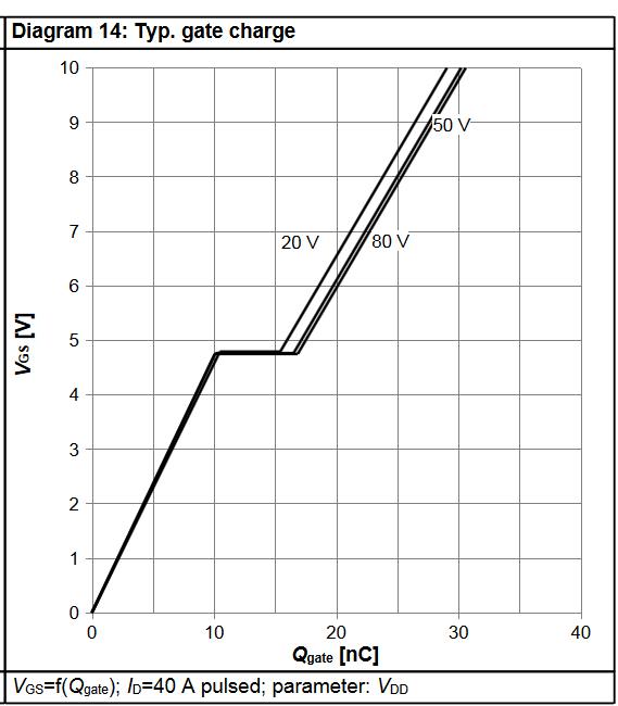
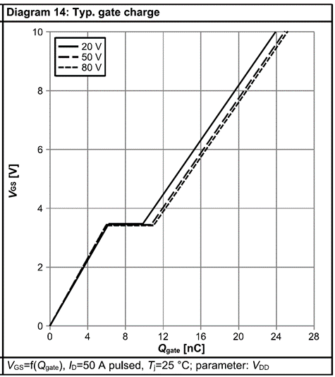
    1. Please use the LM5143 quickstart calculator to check losses. VCCX should not be left unpowered with a cap to GND (as its voltage can float up -- if it exceeds 4.3V, the VCC subregulator will switch off.). The VCC current is Qg*Fsw for each FET, where Qg is the gate charge at Vgs = 5V taken from the MOSFET data sheet. The Vin*Ivcc power loss can be quite high at Vin = 50V.

    2. Vin should come up before VCCX, as there is a diode from VCC to VIN that may conduct if VCC > Vin.

    Regards,

    Tim

  • Hi Tim:

         Thank you for your replay. Your response has addressed our question. Could you please help us reply to Q2?

    • Q2: When startup protection is triggered and VOUT does not output, how can we restore normal operation? Or does this indicate that the LM5143A-Q1 has been damaged?

    Regards,

    YUMING

  • Hard to know for sure. Can you startup into no load?

  • Hi Tim:

       Thank you for your replay. We are currently verifying the output voltage stability of a 2-phase buck converter. The output voltage is 15V, and it remains stable as the load current increases from 1A to 10A. However, once the load reaches 11A, the output ripple becomes significantly larger. We would like to understand how to modify the design to reduce the output voltage ripple.

       The circuit diagram and test waveform shown above are for the first LM5143A-Q1. The second one has not been uploaded yet.

    Regards,

    YUMING

        EP31103601X00_Polaris_REG.pdf

  • Hi Yuming,

    The BSC070N10NS5 is not suitable here with a 5V gate driver, as it is not a logic-level FET with Rdson rated at Vgs = 4.5V. The Miller plateau is too high, > 4V, whereas it should be ~3V. Can you use 60V or 80V FETs here? See the LM5137 EVM for 80V FET part numbers. This may also be causing the stability issue.

    Also, I recommend completing the quickstart calculator to check stability. Make sure to derate ceramic Cout with voltage.

    Regards,

    Tim

  • Hi Tim:

       Thank you for your reply. As you mentioned, the Miller plateau is indeed too high, so we replaced it with the ISC0805NLS. We first paralleled an 1800 µF electrolytic capacitor to the Cout, and indeed, the Vout ripple varied within the normal range.

    We would like to know if you have any further suggestions. Thank you.

    Regards,

    YUMING

  • Hi Yuming,

    Why so much Cout? 1.8mF seems really high. Better to use ceramic and a small-to-medium anount of electrolytic if needed.

    --

    Tim

  • Hi Tim:

           Thank you for your suggestion. At present, we have only used an electrolytic capacitor to determine that the output capacitance may be insufficient, which results in a larger output voltage ripple. Next, we plan to remove the electrolytic capacitor and use a lead-acid battery instead, so that the 15 V output charges the lead-acid battery.

    We are unsure what impact this might have. Do you have any suggestions?

    Regards,

    YUMING

  • You will need a CC circuit for a battery-type load. Take a look at the CC/CV function in the LM5190 controller.

  • Hi Tim:

          Thank you for your suggestion. We will continue our testing, and will reach out to you again should we have any further questions. Thank you.

    (Please feel free to close this issue for now.)

    Regards,

    YUMING

  • Okay, thank you.