This thread has been locked.

If you have a related question, please click the "Ask a related question" button in the top right corner. The newly created question will be automatically linked to this question.

LMG1210: Overshoot at PWM Output During LMG1210 Simulation – Need Support

Part Number: LMG1210

Tool/software:

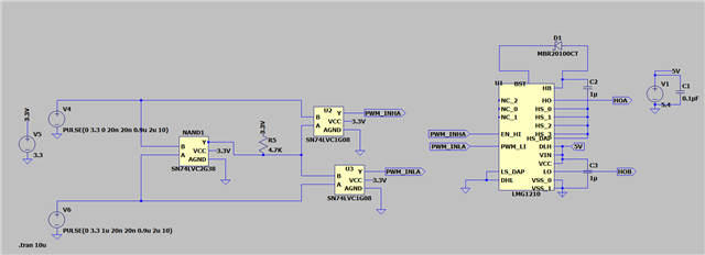
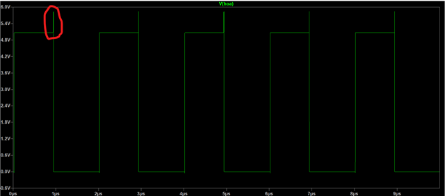
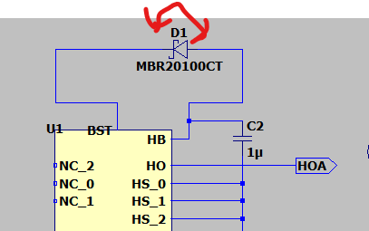
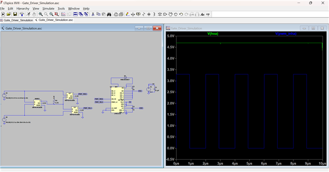
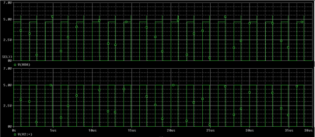
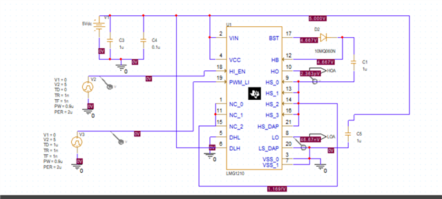
I’m currently simulating the LMG1210 gate driver IC and observing an overshoot at the PWM output during switching. I’ve reviewed the datasheet and application notes but couldn’t pinpoint the root cause.

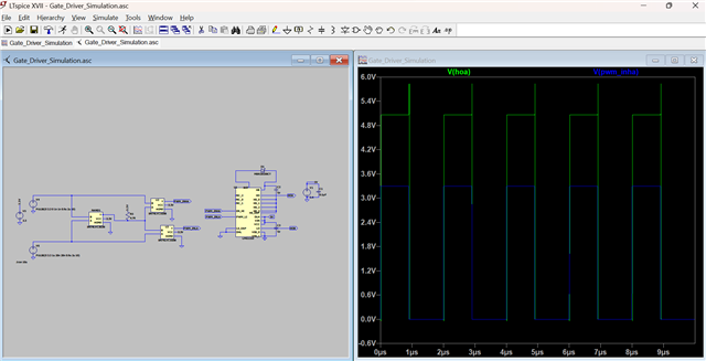
Could you please help me understand why this overshoot is occurring and suggest ways to mitigate it? I’d appreciate any guidance or recommended simulation practices to resolve this issue. I have attached snap of the 

LT spice Simulated circuit and Output .


  • Hello,

    The polarity of the bootstrap diode is incorrect. It should be flipped.

    Also try leaving the HS_DAP pin disconnected. There is an issue with this pin in the model.

    Thanks,

    Walter

  • Thanks for the response.

    I simulated the circuit even after flipping the diode, but I’m still observing the overshoot voltage.

    I also tried disconnecting the HS_DAP pin, but I am getting continuous DC output voltage.

    Kindly provide your suggestion to resolve this issue

  • Hello,

    Can you try simulating the model in PSpice for TI? PSpice is the simulator we design our models for and cannot guarantee complete compatibility in another simulation program.

    Thanks,

    Walter

  • Hello,

    The reason for the continuous output voltage is HS needs to be connected to ground when not being used as a floating high side driver. If the circuit is not configured as a half bridge driver then HS needs to be grounded.

    Thanks,

    Walter

  • Hello

    I tried simulating the circuit using PSpice for TI, and I’m observing an overshoot at the end of the pulse. This behavior appears on both the high side and the low side of the signal.

    Could you please help me understand the reason behind this overshoot?

    V(V2:+) - Input High side PWM pulse

    V(HOA) - High side PWM output signal

    Simulated circuit:

  • Hello,

    I've recreated the simulation and have replicated the issue. This appears to be an issue with the timing in the internal model output allowing a small overshoot duration. Adding a load such as a FET or capacitor to the output reduces the overshoot. The overshoot should not cause much issue when used with an output load in simulation

    The team will look into fixing this model issue in the next revision.

    Thanks,

    Walter