LMZ23608: Possible causes for regulation fault with LMZ23608

Part Number: LMZ23608

Tool/software:

Hello,

I have an issue with a LMZ23608 Simple Switcher device that I have designed into a production board.  At the moment, I only have one fault out of a batch of 50+ boards in the field so I am not too concerned, but I would like to know what the possible fault cause is.

Design

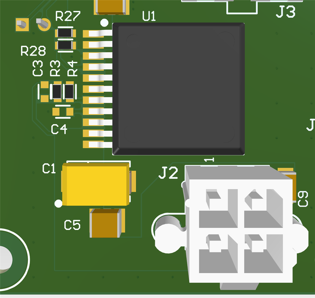
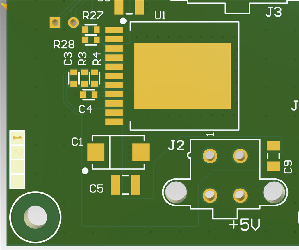
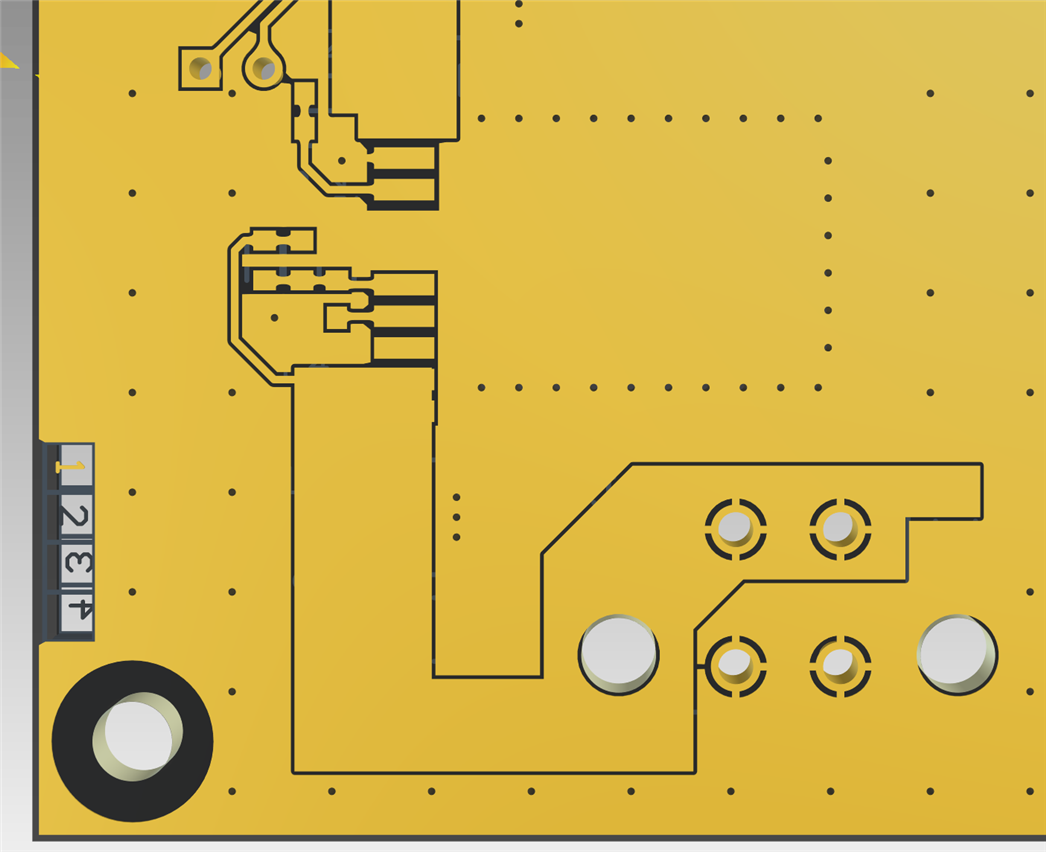
The device is designed to provide a regulated 5V supply from a fixed 24V DC input (provided by a separate AC/DC PSU).  The circuit is shown below:

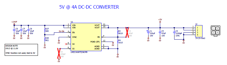
R3 and R4 provide feedback to give an output voltage of 5V.  R27 and R28 provide an enable signal that ensures regulation only starts when VIN is >11.6V.

C1 and C5 provide the necessary output capacitance, C1 is Kemet part T520Y337M010AHE015 and C5 is Kemet part C1210C476K8RACTU.

All resistors are 1% tolerance.

Observations from failed PCB

  • When 24V is applied to the PCB, the 5V rail reads ~4V output, as measured with a DVM.  The same is observed with and without load.  For test purposes, a 1A load provided by an electronic load device.
  • Measuring the FB node (pin 7), the voltage here reads ~660mV and not the 800mV expected from the datasheet.
  • Leaving the power supply connected for a short while, the output voltage steadily increases as does the voltage at the FB node.
  • Spraying the device and surrounding parts with freezer spray does not affect the output behaviour at all.

I've attached three oscilloscope captures showing the behaviour over time.  Yellow trace is the FB node, measured directly at the pin using a tip and barrel connection to the board to minimise loop inductance.  Blue trace is the output from the device.

Figure 1: No load on output:

No Load output (Y = FB, B = 5Vout)

Figure 2: 1A load on output.

1A load (Y = FB, B = 5V out)

Figure 3:

1A load on output, 5V output rail is AC coupled to show ripple behaviour.

A normal device on the same PCB design does not exhibit this behaviour and has a ripple voltage of ~50mV pk-pk.

Questions

What could cause the observed behaviour?

Has the internal reference been damaged inside the LMZ23608?

Are there any other tests I can perform to diagnose this issue further?

Thanks for your help in advance.

Regards,

Simon

  • Hello,

    Can you also share the layout?

    Is the device properly soldered to the board?

    Best regards,

    Ridge

  • I cannot share the whole board layout.  I have attached some screenshots from the CAD.  This is a four layer board with 2oz copper on outer layers.  The idea is to conduct as much heat into the copper and radiate that away into the enclosure.  Our max ambient operating temperature for the product is 40C, the unit that failed was never operated in more than 25C.

    Stack up:

    Components - Top layer.

    Top Layer with no components (showing pads - paste mask is equivalent).

    Top layer copper.

    Inner layer 1 copper (GND):

    Inner layer 2 copper (GND):

    Bottom copper layer (GND):

  • Hello,

    Thanks for sharing the layout.

    Have you tried swapping a known good unit to the board? This would help confirm if the board or device is the issue.

    Are there any other loads on the output aside from the 1A e-load?

    Best regards,

    Ridge

  • There's nothing else on the board that is connected to the 5V rail.  This board is solely used as a DC-DC converter board from the mains PSU to provide 5V to another PCB; 24V in and 5V out.  It was designed to replace a quad output AC/DC mains PSU that has gone obsolete.  The test was made with this DC-DC converter board in isolation.

  • Have you tried swapping a known good unit onto the board?

    Best regards,

    Ridge

  • Hi,

    No I haven't because we do not have the facilities to remove such a large component and get sufficient heat into the board to cause the solder joints to melt.

    As I said, this is the only active device between 24V input and 5V output.  By changing the component, all we are doing is checking that the passives are correct and I cannot imagine how the passives would cause the symptoms that I have observed and documented.

    Can you provide more insight into what could cause the observed behaviour?  Do you agree with the idea that the reference within the simple switcher has become damaged and is not providing a constant 0.8V as it should?

    Regards,

    Simon

  • Hi Simon,

    Ridge is OOO he will reply on Monday.

    Thanks,

    Andrew

  • Hi Simon,

    Swapping a known good unit would help us understand if this specific board is what is causing the device to behave abnormally. If a known good unit works properly on the PCB, then we know there are no issues with the board which could have caused damage to the device.

    Does the 24Vin supply ever overshoot? Do you have a waveform of the input voltage?

    Do you know the soldering profile of the PCB manufacturer?

    Could you share an image of the physical board? Do you measure or notice any shorts on the PCB?

    We need to understand if there is anything which has been done to this device which could cause it to misbehave this way. Since it appears that this issue was observed as soon as the board was turned on, it could be that something with the test setup caused this issue as well. It could also be a soldering issue. If the board is not soldered down to the board properly it may not function as intended.

    Best regards,

    Ridge

  • Dear Ridge,

    The 24V supply is taken from a Traco mains power supply and does not overshoot at all.  Whilst I am away from the office, I do not have any access to the unit but I can assure you I have measured the output of this supply in the past and it behaves as you would expect it to.

    To make the situation even clearer, this board HAS been working and it's only in the recent past that we have found that the device has fails.  The board was produced in 2022, so the PCB and device have been in service for nearly three years.  I can see how you came to the assumption that this board had failed in its infancy from the words I put in the opening post, but please see that this design is in production right now and this is the only failure in more than 50 installations world wide.

    All of the suggestions you are making have already been taken into account.  Naturally, as an engineer with more than 25 years' experience in designing and testing industrial electronic products, I have checked for dry or poor solder joints, shorts, poor manufacturing and the rest.  The schematic attached in the first post shows you ALL of the components on the board that are associated with the 5V rail.  If I had the facilities to remove the device and replace it with a known good part AND I thought that was worth while, given that ALL the other components are passives, then I would have done that.  I made the post to this forum because I had exhausted all of the usual avenues of investigation into component failure and I am now seeking expert advice and insight into the internal workings of the LMZ23608 part that I cannot glean from the datasheet.  I do hope that TI can help me in this endeavour. 

    Kind regards,

    Simon

  • Hello Simon,

    At this point, I think the device should be sent to us following this process: https://www.ti.com/support-quality/additional-information/customer-returns.html

    We can then test in our own faculties to find the root cause of this problem.

    Best regards,

    Ridge

  • Closing this thread due to inactivity.