A related question is a question created from another question. When the related question is created, it will be automatically linked to the original question.
If you have a related question, please click the "Ask a related question" button in the top right corner. The newly created question will be automatically linked to this question.
What is the percentage of devices with this behavior? Noise can originate from many different areas, can you identify where on the PCBA the noise is originating from?
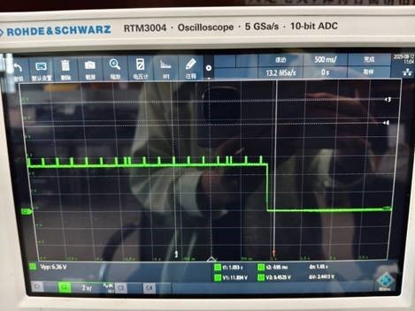
The oscilloscope captured the voltage waveform of RCET during charging (with a load of 500mA/5V), showing periodic pulses. The frequency of these pulses is the same as that of the heard noise. The pulse period is approximately 250ms, and when the pulse is expanded, it appears as a 2kHz signal (which should be an ASK modulated signal).
The specification indicates that the RECT pin will not have such pulse signals during stable charging. However, in actual testing, these pulses exist, and their amplitude decreases as the load current increases. Please help troubleshoot this issue. Thank you!
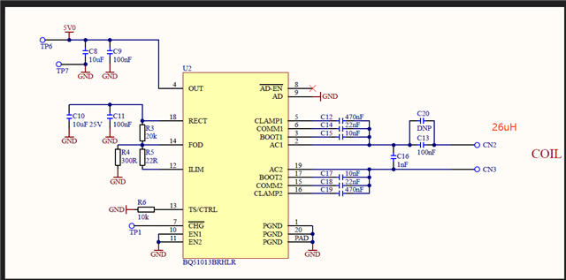
The schematic diagram is as follows. For the capacitors of COMM1/COMM2, I once changed them from 22nF to 47nF, and the pulse amplitude became larger. The resonant capacitor uses X7R, and I also tried replacing it with NP0, but there was no improvement.
I have seen the same problem in other TI cases. Link: BQ51013B: Buzzing noise/FOD limits - Power management forum - Power management - TI E2E support forums This case also has abnormal pulses and noise in RECT. One of the replies points out: It seems that the communication data packets between TX and RX are corrupted. Is there any way to verify the communication data packets?
This case also has abnormal pulses and noise in RECT. One of the replies points out: It seems that the communication data packets between TX and RX are corrupted. Is there any way to verify the communication data packets?
The indications of communications issues would be the output dropping to 0V followed by a restart. The drop out to restart is about 40mS.
The oscilloscope captured the voltage waveform of RCET during charging (with a load of 500mA/5V), showing periodic pulses. The frequency of these pulses is the same as that of the heard noise.
Looking at the above scope capture unit is operating for over 4 seconds then turns off with no restart. Does not look like a communications issue.
The schematic diagram is as follows. For the capacitors of COMM1/COMM2, I once changed them from 22nF to 47nF, and the pulse amplitude became larger. The resonant capacitor uses X7R, and I also tried replacing it with NP0, but there was no improvement.
This sounds correct, larger value capacitors will increase the shift in resonate freq.
The standard value of 22nF is good but smaller value COMM capacitor may work also. COMM value is about 10% of the resonant capacitor, in this application about 10 to 15nF would probably work also.
Another capacitor to check is C8 on the output, suspect the output may have some ripple on it also.