Tool/software:
Dear TI Support Team,
I would like to ask a follow-up question regarding the TPS65313-Q1, which I am planning to use as a PMIC in my design.
Previously, I suspected that the issue was caused by providing only 5V to the WAKE pin, but I have since revised the circuit to ensure the WAKE pin receives approximately 11.5V (as measured with an oscilloscope). Despite this, I still do not observe any output from Buck1, Buck2, or the Boost converter — i.e., no 3.3V, 1.2V, or 5V outputs.
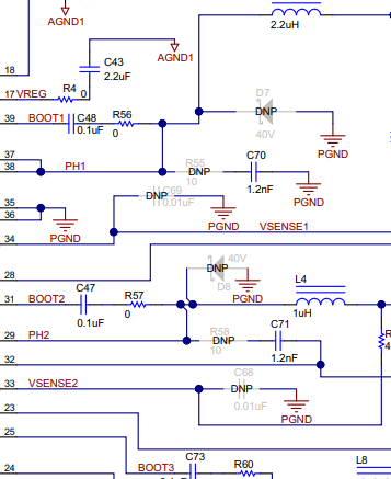
I designed my custom board based on the schematic provided in the EVM kit datasheet. However, I am unsure why the regulators are not turning on.
From what I can tell, there seems to be no switching activity at the Boot1 output, and I cannot identify the reason for this behavior.
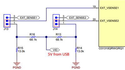
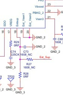
Since I do not plan to use any external power source, I connected Ext_Vsen1, Ext_Vsen2, and Extsup to GND — just as shown in the EVM when those functions are unused. However, this setup still does not result in any output voltages, and I am also not observing any waveform on the VREG pin.
I would greatly appreciate your support in identifying what could be going wrong.
I will attach my schematic for your reference.
Please note that this setup is intended only for testing the power outputs, so the MCU is not connected to the board.
SPI communication is also not connected.
Pins 7 to 11, as well as all SPI-related pins, are left unconnected.
As mentioned earlier, I designed the schematic by closely referencing the TPS65313-Q1 EVM kit.
It should be nearly identical to the EVM.
If there is anything incorrect or missing in my implementation, I would greatly appreciate your advice or suggestions.
Thank you very much for your help.
Sincerely,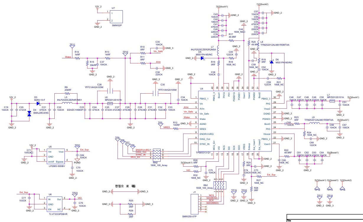
Lee