Tool/software:
Dear TI Community,
I am currently working on a 1000 W Continuous Conduction Mode (CCM) boost PFC design using the UCC28180 controller. The circuit performs well at light to medium loads, maintaining a power factor (PF) of 0.99 up to approximately 700 W. However, as the output load increases beyond 750 W, I observe a gradual drop in PF to around 0.95.
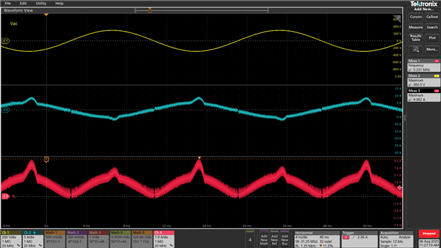
Upon probing the waveforms with an oscilloscope, I noticed that both the inductor and input current waveforms begin to show peaking near the AC line voltage peaks. This distortion seems to coincide with the observed drop in PF.
To support this observation, I have captured and arranged waveforms chronologically at increasing output loads of 1.9 A and 2.25 A.
Key design parameters:
-
Vin: 180–265 VAC, 50/60 Hz
-
Vout: 350 VDC
-
Pout: 1000 W
-
Rsense: 250 mΩ
-
Boost Inductance: 410 µH at nominal current
-
Switching Frequency: 100 kHz
I would appreciate any insights, recommendations, or reference material to help me better understand and address this behavior, particularly regarding waveform distortion and current shaping near full load.
Thank you in advance for your time and support.
Best regards,
Sourov Roy
Iout=1.9A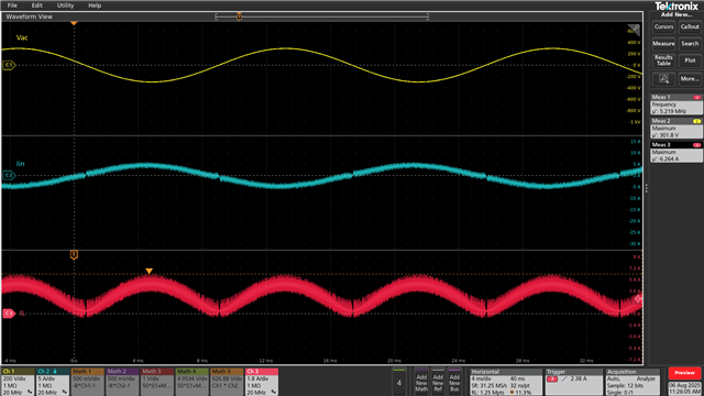
Iout=2.25A