Tool/software:
Hello All,
I am currently evaluating the UIR sensor BQ79731-Q1 with the isolation monitoring feature for our 96V and 800V BMS design and have reviewed the datasheet and design documents, which reference a 500V system. I have few queries and would appreciate your insights to clarify the following points:
1. The datasheet indicates that SW1 is used to measure isolation resistance. Could you elaborate on the purpose of SW3 in this context? Additionally, could you explain how this method ensures compliance with ASIL requirements? Also, how to decide to select Automotive Isolated Switch (TPSI2140) or MOSFET for SW1, SW2 and SW3?
2. The equations are not provided in the datasheet, so I have referred design document (Application Note: Insulation Resistance Detection for HEV Applications) for the equations above.
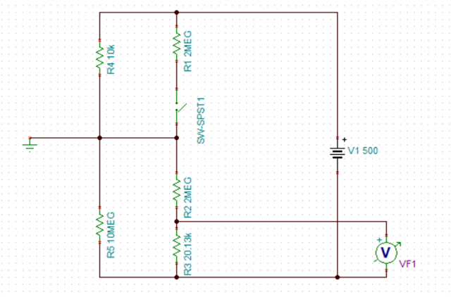
The provided equations assumes that the current through parallel branch (R1 and Risop) and the parallel branch ((R3 + R2) and Rison) will be same, with VF1 considered as the voltage drop across the parallel combination of (R3 + R2) and Rison. However, it appears in the design document that VF1 is the voltage drop across R3 alone. Could you clarify whether the assumption that VF1 applies to the parallel combination is accurate?
3. Chassis ground and the HV pack negative are at different potentials and all nodes in the circuit are at distinct potentials.
4. Could you provide a detailed derivation of the equations used for the isolation resistance measurement to help us better understand? I have provided a table in the trailing mail which have the measurements of Rison and Risop and in some cases there is deviations in the measurement values and assumed values, which I have highlighted red. We want to understand the reason for the deviation.
5. I have performed simulations and calculations for the resistance values under three conditions for same 500V reference system. For the second condition, the calculated values do not align with the assumed values. Could you provide the guidance to understand this difference?
| Condition 1 | |||
| Assumed | Calculated | ||
| Risop (ohms) | Rison (ohms) | Risop (ohms) | Rison (ohms) |
| 10000000 | 10000000 | 9914281 | 10079653 |
| 10000000 | 1000000 | 9873257 | 995679 |
| 10000000 | 500000 | 9869418 | 498000 |
| 10000000 | 100000 | 10050006 | 101578 |
| 10000000 | 50000 | 9884129 | 49912 |
| 10000000 | 10000 | 9887389 | 9981 |
| Condition 2 | |||
| Risop (ohms) | Rison (ohms) | Risop (ohms) | Rison (ohms) |
| 10000000 | 10000000 | 9914281 | 10079653 |
| 1000000 | 10000000 | 984899 | 9251869 |
| 500000 | 10000000 | 484155 | 8562481 |
| 400000 | 10000000 | 420999 | 14055307 |
| 300000 | 10000000 | 279677 | 7227793 |
| 265000 | 10000000 | 264336 | 9724990 |
| 250000 | 10000000 | 236057 | 7725289 |
| 245000 | 10000000 | 239631 | 9163246 |
| 240000 | 10000000 | 243335 | 11216698 |
| 170000 | 10000000 | 208382 | -158065710 |
| 100000 | 10000000 | 77711 | 3635120 |
| 50000 | 10000000 | 0 | 0 |
| 10000 | 10000000 | 0 | 0 |
| Condition 3 | |||
| Risop (ohms) | Rison (ohms) | Risop (ohms) | Rison (ohms) |
| 10000000 | 10000000 | 9914281 | 10079653 |
| 1000000 | 1000000 | 999554 | 999214 |
| 500000 | 500000 | 504279 | 504969 |
| 100000 | 100000 | 98316 | 98589 |
| 50000 | 50000 | 48561 | 48704 |
| 10000 | 10000 | 16057 | 16106 |
6.. The reference calculations and design in the documents are based on a 500V system. Since we are designing for a 96V and 800V BMS, could you provide guidance on how to select appropriate values for R1, R2, and R3 to ensure compatibility and optimal performance for our 96V and 800V voltage system?
7. Is there any other document we can refer to?