This thread has been locked.

If you have a related question, please click the "Ask a related question" button in the top right corner. The newly created question will be automatically linked to this question.

TPS3825: issues with an external 0.1uF capacitor at /MR input pin

Part Number: TPS3825

Tool/software:

Dear TI support,
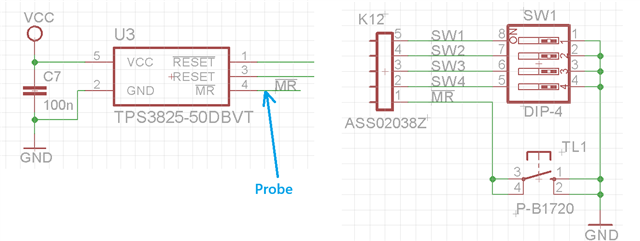
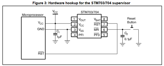
we are using the TPS3825-50 with just a push button at /MR (TPS3825 includes an 90kohm pull-up resistor). The /MR input pin seams to be sensitive as there are unwanted resets during ESD events. We decided to add a 0,1uF capacitor to /MR pin (as suggested in many application notes).
But a new issue encountered. When I press the puch button, the /MR signal remains at cca 1V after releasing the button (the voltage at /MR will not raise - capacitor will not be charged throw internall pull-up) .
If I the capacitor is not populated than the manual reset works well. If I add an series resistor (100R) along with the 0,1uF capacitor than the manul reset works well.
I undesratnd that if I push the button than the capacitor will be shorted to GND (large discharge current flows) but is the issue related to the current / negative voltage or rise/fall time at /MR pin?
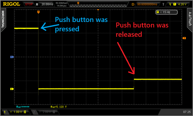
Thank you for the explanation.
Best regards, Tomas.

  • Hi Tomas,

    A few questions to help clarify the situation:

    Could you provide a schematic of the circuit that you used to capture the oscilloscope screenshot?

    Which exact app notes suggest adding just a capacitor to the MR pin for the purpose of ESD protection? A more typical approach would be to use TVS diodes for ESD protection.

    Thanks,

    Henry

  • Hi Henry,
    please see the schematic for clarification. 
    We design and manufacture equipment in the field of oil industry (Filling stations, Automatic fuel dispensers and other solutions for fueling customers).
    The 0.1uF capacitor along with an 100R resistor in series solved our unwanted resets (not only at ESD events). I'm surprised about the behaviour if only a 0.1uF capacitor is connected at /MR pin.
    From the datsheet (TPS3825) I can see that the "glitch immunity" (minimum pulse width at /MR) is 1us.
    Recommendation from TPS31xx (Texas Instruments): 8.3.2: If /MR is driven from long cables or if the device is used in noisy environments, connecting a 0.1-μF capacitor from MR to GND provides additional noise immunity. Second recommendation from STMicroelectronics.


    Thanks, Tomas

  • Tomas,

    Thanks for the schematic. I don't see any obvious issues with your circuit. 

    While we look into the issue further, could you provide an oscilloscope capture showing VCC, /RESET, and /MR pins when there is a 0.1μF capacitor between /MR and GND?

    -Henry

  • Hi Henry,
    please see below the captured signals. Horizontal scale 20ms/DIV vs. 2us/DIV (Zoom).

    Tomas