This thread has been locked.

If you have a related question, please click the "Ask a related question" button in the top right corner. The newly created question will be automatically linked to this question.

LM3478: LM3478

Part Number: LM3478
Other Parts Discussed in Thread: LM5155

Tool/software:


Hi TI experts!
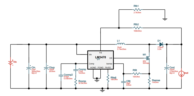
I have encountered an issue with the boost converter based on the LM3478. I've used Webench to design the schematic, so I was pretty sure all should've work well. But it doesnt. 
The drive output is constantly high, thus the mosfet is on and shorting the circuit through the inductor. Whatever the input voltage is, the duty cycle is always 100%. There are no load at the output.
My power supply triggers its protection at 5A. After experimenting a while, the only way I could get duty cycle less than 100%, is leaving the Isense pin floating. Perhaps, the Isense resistance is too small? Or there is another issue with the IC or the design?
Please advice! 

  • Update.
    I was right! The current sense resistor was too small to start up the IC properly. I've put two 7mOhm resistors in series, and the converter started working.
    But there is another issue. Instead of Webench (which let me down twice) I've used the LM3478-88_Quickstart_Calculator_Boost_V1_1_0. 
    I've lowered the frequency to 500 kHz and got the result. With the recommended components for the loop compensation, the phase margin is 101 degrees. Isn't that too much?
    Please help to calculate proper Rcomp, Ccomp and Chf values! The calculator file is attached.
    Thanks!

  • Hi Nazar,

    Thanks for using the e2e forum.
    In general, I recommend using the quickstart calculator over webench. While the basic equations are the same, the quickstart tool takes more value entries and allows for more modification.

    I am glad to see that design is running with a 14 mOhm sense resistance.
    For compensation, we recommend at least 60 degree phase margin for a stable system, but there is not really an upper limit.
    However, for your input is see a very narrow gain margin of ~7dB. (The gain at crossover frequency of the phase).
    If the gain curve is rather flat at the area where it crosses the 0dB mark, this is also bad for stability.
    The root cause for this comes from the high ESR of the capacitance you put in (80mOhms).

    For output capacitance, we recommend low ESR ceramic caps to filter the switching noise. (Bulk caps are still good for compensating strong load transients, so in the end most designs use a combination of ceramic AND bulk caps)
    If you reduce the ESR entry in line 42, you will see that the gain curve becomes much steeper and gain margin increases, but also phase margin will also decrease.
    Unfortunately, the calculator only allows one parameter for capacitance and according ESR.

    For example, if I enter a capacitance of 100uF and reduce the the ESR to 10mOhm, the recommended parameters and bode plot are updated like this:

    Some additional literature on loop compensation are found here:
    https://www.ti.com/lit/an/slva381b/slva381b.pdf

    Please let me know if you have additional questions on this.

    Best regards,
    Niklas

  • Hi Niklas!
    Thanks for the reply!
    I've made changes to the schematic that you suggested. It works stable up to 1.4A load. Larger than that the output voltage drops to 42V and keeps dropping with the current increasing. 

    But that's not the main issue! The IC is having trouble with starting up properly. It just opens the mosfet shorting the Vin circuit through the inductor. I've run out mosfets as they keep burning out! I can't increase the current sense resistor any more as this will reduce the output current. It is lower than I need anyway. I'm willing to give up on the LM3478 as these things just shouldn't happen. The IC has faulty design. It just shouldn't have a 100% duty cycle for longer than 1 clock period.

    Any ideas how to deal with this? Otherwise, I'm moving on to a different boost controller.

  • Hi Nazar,

    I am sorry you have still problems with the design.
    A major disadvantage of LM3478 is that is has no adjustable softstart time.
    The internal softstart time is fixed to 4ms.
    If you build a design that needs to power up under active load conditions and you have output capacitance, that needs to be charged on top,
    the device quickly runs into overcurrent protection and the output voltage never comes up.
    In your case, it sound like the full system is even becoming unstable and the MOSFETs burn due to inductor saturation.

    If you want to confirm if the short softstart time is the root cause here, you can do a test where you start up without load and then add the load once VOUT is stable.

    As the softstart time cannot be increased, the LM3478 device gives little options of avoiding the high inrush current, besides starting up without load or decreasing output capacitance.

    Newer device like LM5155 are more robust, have max duty cycle limitation and have an adjustable softstart time to limit the inrush current.
    Unfortunately, LM5155 is not pin2pin compatible with LM3478, so a layout change would be necessary.

    Best regards,
    Niklas