This thread has been locked.

If you have a related question, please click the "Ask a related question" button in the top right corner. The newly created question will be automatically linked to this question.

LM5175-Q1: Ripple is detected both input and output

Part Number: LM5175-Q1
Other Parts Discussed in Thread: LM5175

Tool/software:

Dear TI experts,

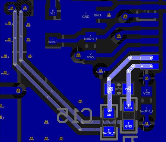
My customer tests LM5175-Q1 in their own PCB, and they found that ripple is detected both input and output.

I think layout is something wrong, so I want you to check schematic and layout.

Just these files are confidential, so I want to send these files by private message.

Could you send me the friendship request? Then I will give schematic, layout and some test results.

Best regards,

Chase

  • HI Chase,

    you can send this to me on private message. Just hover with the mouse over my avatar and then select send private message.

    Once done please drop a note in this thread so that i know to check my private messages.

    Best regards,

      Stefan

  • Dear Stefan,

    Thank you for you support.

    I sent you a message, please check it.

    Best regards,

    Chase

  • Hi Chase,

    there are a few items which should be checked first.

    - The slope compensation capacitor is much higher then recommended

    - Thermal pad of the LM5175 has thermals which will have bad thermal connection and also add inductance

    - connection of the Sense Resistor R694 is not done as Kelvin connection. This can add additional noise in the sensing signal and disturbe the regulation.

    - phase margin is only 34 Degree

    Best regards,

     Stefan

  • Hi Chase,

    please always drop a note in the thread - otherwise you might not get a reply for days or weeks as private message gets not checked regularly and can not be accessed by the whole apps team.

    - The slope compensation capacitor is much higher then recommended -> I will test the value as same as EVM.

    -> please do not use the value of the EVM but use the value which fits to your design based on the datasheet or quickstart calculator

    - Thermal pad of the LM5175 has thermals which will have bad thermal connection and also add inductance -> Does it mean that thermal pad of LM5175 have a bad connection to GND of PCB? and this bad connection caused additional inductance? Can I improve it through adding vias on GND pad?

    -> Vias can improve but would also use the out side layer for better thermal connection without using thermals for the thermal pad.

    - connection of the Sense Resistor R694 is not done as Kelvin connection. This can add additional noise in the sensing signal and disturb the regulation. -> I checked about Kelvin connection in google. but EVM is also not done as kelvin connection. Could you tell me why and give me ideal example for Kelvin connection?

    -> the EVM has a Kelvin connection to the shunt resistor on CS/CSB

    - phase margin is only 34 Degree -> How can I expand phase margin? Is it possible to change the values on the PCB? Or should I change PCB layout?

    -> phase margin can be adjusted by the compensation (components on the COMP pin) the quickstart calculator can help you on that

    =>  LM5175QUICKSTART-CALC  LM5175 Quick Start Calculator

    Best regards,

     Stefan