TPS40170: converter shuts down on connection to capacitive load

Part Number: TPS40170
Other Parts Discussed in Thread: LM5190, LM5145

Tool/software:

Hello everyone,
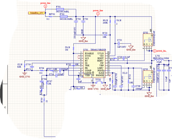
I have implemented the TPS40170 according to the attached schematic. My input is 20 V and the output is 12 V @ 3 A.

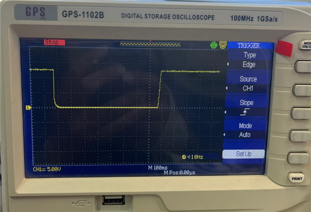
With purely resistive loads the converter works perfectly. However, when I connect an electronic device whose supply input contains a capacitor, the converter momentarily shuts down and then restarts. I captured this behaviour on the oscilloscope — see the first attached image.

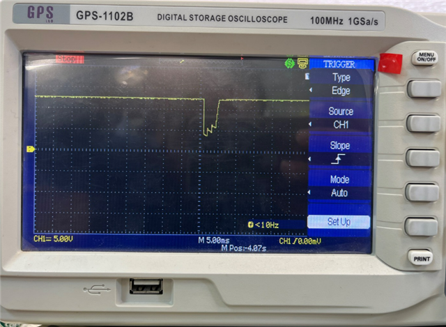
After multiple tests I concluded that the issue is related to current protection / soft-start behaviour. Adding a soft-start capacitor did not fix the problem; in fact it increased the duration the converter stayed off. In the next test I completely removed the soft-start capacitor and also removed the resistor used for current limiting. The result is shown in the second attached image: the converter still shuts down, but the off time is much shorter.

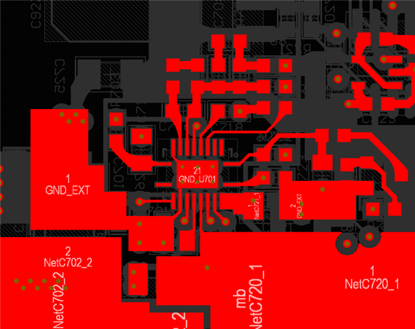
The electronic systems I intend to power are sensitive, and these momentary shutdowns cause serious problems for them. Please advise on possible causes and recommended fixes (e.g. changes to soft-start, current-limit settings, snubbing, inrush control, layout issues, or other design considerations).

Best regards, Jacob

  • Hi Jacob,

    This is current limit engaging due to the capacitive load. Ideally, you would use a CC/CV circuit to limit the current - take a look at the LM5190 controller.

    Regards,

    Tim

  • Thank you for your response. Since the circuit has already been designed, it's no longer possible to change the IC.
    Is there any way I can solve or at least optimize this issue using the existing circuit?
    Would adjusting the parameters or settings of the IC help in any way?

  • Jacob,

    Consider adding an external constant-current (CC) circuit to manage the capacitive load. Otherwise, it is difficult to limit the current spike without triggering the current limit. The TPS40170 only provides output voltage regulation.

    I recommend filling out the design calculator for this controller to check where is the current limit setpoint relative to the full-load current rating.

    PS: the LM5145 is now preferred over the TPS40170 - same voltage-mode architecture.

    Regards,

    Tim

  • My circuit has already been designed and the PCB has been manufactured, so hardware changes are no longer possible. I originally designed this circuit two years ago, and unfortunately I have only recently noticed this problem.

    If you think it might be possible to solve the issue by changing parameters of this IC, I would greatly appreciate your help. Also, if there is any way to completely disable the current protection, that would be helpful to know.

  • Maybe increase the current limit setpoint (but don't go above the inductor sat current rating).

  • My ILIM resistor is currently 150kΩ, and the capacitive load connected to it is around 220µF. The same issue still persists and has not been resolved. A 220µF capacitor is not a large value, so this behavior of the converter is quite surprising to me.
    In any case, increasing the ILIM resistance hasn’t helped. I would appreciate it if you could suggest another solution to resolve this issue, as changing the IC is not an option at this moment.

  • 220uF is a huge value at 12Vout, especially if the cap is instantaneously connected. Is there a way to connect the capacitive load gradually or before startup? Otherwise, there will be a huge current spike into the cap, resulting in power stage component stress and ground bounce. Note also that compensation needs to be verified both with and without the cap to ensure stability.

    --

    Tim

  • The output capacitor of the converter is around 60 µF. The converter is connected to an external electronic device, which has at least a 220 µF capacitor at its input. Unfortunately, that device is not accessible to me, and I can’t make any changes to it.

    On the other hand, reducing the converter’s own output capacitance isn’t really an option either, since it would negatively affect output ripple, so I believe we’re stuck in a bit of a corner here.

    The converter output is connected to several external devices via programmable switches (MOSFETs). When one of these switches turns on, the converter connects to the device—which likely has a large capacitor on its input. At that moment, the converter shuts down, likely due to inrush current or overstress, and this behavior is causing issues for both my board and the customer’s board.

    Do you have any suggestions or recommendations for handling this situation?

    With your help, I hope we can find a solution to resolve this issue. I would really appreciate any advice or guidance you can provide.

  • I have been using this converter for a couple of years, and it has worked very well for me. However, one of my clients has noticed this issue, which has now created a significant challenge and crisis for me, potentially causing substantial losses.

    I would sincerely appreciate your help in resolving this matter.

  • Is it possible to use a load switch to effectively soft start the attached load?

  • I’m using a transistor to control a MOSFET, which in turn switches power to the loads. There are several of these switches, each connected to different loads with varying power requirements.

    At most, I could add a capacitor at the output of the MOSFETs to make the power-up a bit smoother, but I doubt that would be very effective for this case.

    Also, the board has already been designed, so I need to keep changes to a minimum.

    By “load switch”, do you mean a specific component or a particular circuit design?

  • Is there anything that can be done using the converter itself? Because I think the switches would require significant modifications to address this issue.

  • Have you got a waveform to see how severe the current spike is? Send on the PCB layout as well.

    Anything you can do to slow up the application of the load is helpful.

  • this is my pcb layout

  • Do you think adding a snubber to this converter would improve the situation or not?

  • A snubber slows down the switching edges. I doubt it would have any impact.