TPS769: New/legacy chip and output capacitor

Part Number: TPS769
Other Parts Discussed in Thread: TPS7A24

Tool/software:

Hello,

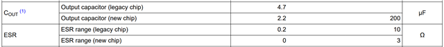
I'm working with TPS76933 LDO. Datasheet shows that there are two variants of this chip available - new and legacy. Table 8-1 shows that new chip has M3 suffix in the name, however in Packing information table there is no any part with M3 in the name. Can somebody confirm that this means that this chip is not in production yet?

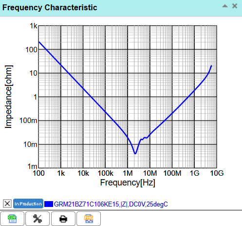
As an output capacitor I'm planing to use 10 uF/16 V capacitor made by Murata, with part number: GRM21BZ71C106KE15L. Should this capacitor work with legacy chip without any additional resistor (like 1 Ohm) added in series?

Thanks!

  • Hi D3jun58,

    Thank you for asking us! We shouldn't be shipping new parts for the TPS769 without an M3 part number, but give me a few business days to confirm. I know we are currently shipping the automative qualified parts (TPS769-Q1) under the M3 label.

    The capacitor should definitely work for the new chip, however I am worried about it satisfying the ESR requirement of the legacy chip.

    When I inspect the impedance vs frequency curve for the P/N via Murata's SimSurf tool, it dips below the 200mΩ value (which wouldn't happen with 200mΩ ESR). 

    Therefore I cannot guarantee it will remain stable with that output cap on the output over the entire recommended operating range.

    Best,

    Gregory Thompson

  • Hi Gregory,

    thanks for reply. I changed to TPS7A2433 LDO, since it looks more reliable choice. It is almost pin to pin compatible with TPS76933, I just needed to change where the EN pin is tied to (TPS769 has negative logic on that pin). One capacitor - 10 uF/ 16 V at the input and one - 10 uF / 16 V at the output look completly fine, since I can't see any restrictions regarding minimum ESR of output capacitor for that LDO. Minimal effective input capacitance is suggested to be 1 uF, however a higher capacitance would also be fine.

    Another difference between TPS7A24 and TPS769 is that a connection of NC pin to ground is suggested because of more efficient heat dissipation. However, I'm expecting of no more than 15 or 20 mA current in pulses and average below 10 mA, it should be fine also without that connection.

    Is there any idea how much the parallel connection of the small capacitor (let say 100 nF which has even smaller ESR than 10 uF) with 10 uF at the input of LDO helps in improve of output noise performance? I'm thinking about using additional capacitor at the input since inductive load would be supplied from the same power supply. Question is how can I at least simulate these conditions to find out if there would be much difference or not?

    Thank you.

  • Hi D3jun58,

    The TPS7A24 doesn't have an ESR requirement, and the datasheet recommends low ESR capacitors anyways. This will work.

    You will be fine without grounding the TPS7A24's NC pin, the effect is pretty small anyways (the bond wire to that pin conducts significantly less heat than the large thermal pad directly attached to the die) and your power dissipation is too small to push it into thermal shutdown anyways.

    I'm assuming there's an inductive load powered by LDO's input rail, essentially in parallel. Please correct me if I am wrong.

    The concern here is PSRR, especially if you're worried about how the parallel inductive load will affect output. The intrinsic noise is so low that it has to be placed inside a faraday cage to measure without being dominated by ambient EMI i.e. it's negligible when you have measurable input oscillation. Your best option to simulate is probably the public SPICE model. I took a look at the notes inside the SPICE model .lib file from TI.com, PSRR is modeled only by 1st pole and zero. Therefore it will be able to give an estimate of the magnitude of oscillation on the output, though not a perfectly accurate waveform. 

    Below is the measured PSRR from the datasheet, it's just an inverse of the transfer function from input to output (in fact we measure it using the BODE100's transfer function measurement with the input/output channels swapped). The take away is that, depending on the frequency of noise in the input, your output oscillation will be 10-1000x smaller.

    Input capacitance is only as useful as your upstream source impedance, but you can always add a small resistor directly upstream to act as an RC filter. Another way to simulate is to use a current source to represent the LDO at some load and you have a decent approximation of the upstream circuit. Then just divide the oscillation at the high side of the LDO-as-a-current-source and divide it by the LDO's PSRR to get output oscillation.

    The impact of the output circuit (feedback network, Cout/CFF, load) is a little bit more complicated but the basic concept is that the lower the impedance at that frequency, the more the feedback loop can reject it. That's why the trough's in the output capacitor's impedance vs frequency curve show up as peaks in the PSRR at >100kHz. If you look at the below image, you would be modifying Zout, Vout, and AFB.

    Source: PowerPoint Presentation

    A good deep dive into intrsinic noise: LDO Noise Demystified (Rev. B)

    PSRR: Understanding power supply ripple rejection in linear regulators

    Best,

    Gregory Thompson