This thread has been locked.

If you have a related question, please click the "Ask a related question" button in the top right corner. The newly created question will be automatically linked to this question.

TPS92610-Q1: TPS92610-Q1

Part Number: TPS92610-Q1


Tool/software:

Hi,

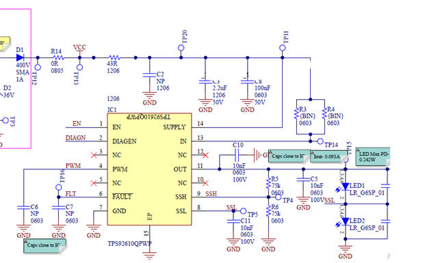
I am using TPS92610Q single channel IC for for TAIL LED function. when diagnostic detect single LED short or open, IC generate 2mA retry current which cause LEDs dimming with very low intensity.

How to resolve this retry current issue.

Regards,

Tanvir 

  • Hello Tanvir,

    The retry current is activated by the faults shown in table 1 of section 7.3.6 of the data sheet. You can stop the retry current and fault diagnosis by ensuring the voltage at DIAGEN is less than V_IL(DIAGEN) or shorted to ground. Shorting DIAGEN will lose the function to detect single LED shorts and opens. Please let me know if this function will work for you.

    Kind Regards,

    Nicholas Alexander

  • Hello Nicholas,

    Thank you for your support,

    Diagnostic I can't Short because I need to detect the failure at set input voltage start from 9v

  • Hello Tanvir,

    Is your goal to ensure the LEDs are completely off when the retry current is flowing? Are you testing using our EVM? How are you testing this function?

    Thanks,

    Nicholas Alexander

  • Hi Nicholas, 

    Yes you understanding is correct..I would like to switch off the LED complete when there is an failure. I had this observation in one my current development project

  • Hello Tanvir,

    How many LEDs are you using and what are their forward voltage? I am currently working with my team to come up with a solution.

    Best,

    Nicholas Alexander

  • Hello Nicholas, 

    Observation is the same if connect 2 or 3 LED in series typical vf 2.8v, I checked at supply voltage from 9v to 16v 

  • Hello Tanvir,

    If you have an MCU connected to the device, then you can use software to achieve the function you want. The retry current is fixed internally and can be disabled by pulling the EN signal low or powering off the device. If the FAULT signal and EN signal are monitored by an external MCU, then you can pull the EN signal low when FAULT is pulled low using software. You will have to pull the EN signal high to check the fault again or to try to use the auto-recover function. If there is no external MCU then we will need to discuss the schematic further.

    Kind Regards, 

    Nicholas Alexander

  • Hello Nicholas, i am not using MCU for fault detection, yes sure we can discuss further with schematic let me know how to proceed with schematic discussion

  • Hello Tanvir,

    What inputs do you have available? Is it only the PWM for the device?

    Also, when a single LED short fault is called, what do you expect the device to do? Should It shut off completely until it is power cycled? Do you want the diagnostics to retry after a certain amount of time?

    Best,

    Nicholas Alexander

  • Hello Nicholas,

    Input to the device is pure dc signal 12V

    pls check below is my schematic.

    when i short or open the LED, devices tries to retry current 2mA and continuously blinking the non shorted or non open LED with very low intensity

    when there is failure in LED , my goal is to completely turn of LED, irrespective device shutdown or still working.

    this LED blinking should not be visible

     ,

  • Hello Tanvir, 

    I have been testing different configurations of the circuit and may have found a solution using logic. I first tested by using a diode from FAULT to EN and DIAGEN to see if any of those would remove the retry current but was unable to stop the current from flowing. When FAULT was bridged to EN or DIAGEN it would pulse low for about 10 microseconds and then go high for 100 microseconds and pulse the full current across the LEDs.

    I do have a logic based solution for this device that enables the device when supply is applied to it and shuts off the device when FAULT pulls low.

    PSpice's transient simulations with a supply voltage ranging from 9V to 16V have worked for this circuit but I have not tested in real life. The SR latch is what holds the memory that a fault has happened. The Power on Reset circuit ensures that the SR latch's output to EN is high each time the power is cycled. The resistor divider connected from supply to FAULT to ensure the latch is properly configured and that the voltage applied to FAULT never goes above the recommended 7 volts. When FAULT pulses low, it is stored in the SR latch as long as the supply is applied to the circuit.

    This schematic will need to be tested with real parts to verify operation. A Schmitt-Trigger may need to be added between the Power On Reset circuit and the SR Latch to help with edge cases.

    If you have any questions, please let me know.

    Kind Regards,

    Nicholas Alexander

  • Hi Nicholas,

    Thank you for your support, let me check with this solution on my physical board if result seems ok I will let you know.

    Regards,

    Tanvir