BQ25798: BQ25798RQMR for Electrolytic capacitor charging with constant current of 2A

Part Number: BQ25798
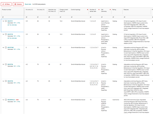
Other Parts Discussed in Thread: LM317, BQ25750, BQ25713, BQ25730

Tool/software:

 I am having a requirement to charge Electrolytic capacitor 24 V , I would like to check if this part can be used for Electrolytic capacitor charging to charge 6x8200uf cap to 24 V with 2A at good efficiency 90% compared to LM317 and program the o/p current to 2A MAX limit

  • Hi Justin,

    This would require greater than 24V*2A=48W input power. Also as explained in https://www.ti.com/lit/pdf/sluaao7 the charger's output current is reduced until the voltage rises above 2.5V.  

    Regards,

    Jeff

  • hi Jeff 

    Thanks for sharing the application note 

    This approach limits my discharging from the Super cap as the discharge path is from VSYS My discharge req is very high 100A can PMID Pin supports higher current ?

    when charger is plugged what is the current limitation on PMID ? is it the same as the charging current ?

    so can I use from  the below parts and tap the load directly from cap pin so that no discharge limitation 

  • Hi Justin,

    Jeff will be out of the office for a little bit, and I will be taking over. I can check the PMID current limitation, but it would not be 100A. This would damage the part.

    For the BQ2575X family of parts, you can charge the capacitor and place a load directly to the capacitor. You can also use the power path functionality of the BQ25750 and have the capacitor separated from the load by back-to-back MOSFETs and turn on those MOSFETs when needed.

    Best regards,
    Michael

  • hi Michael 

    Thanks for your response 

    Regarding the app note Jeff provided there is another type of chargers which can support charging even from lower voltage by proper register writes  is there a software resister  sequence available to do this 

    "Unlike many chargers, the BQ25713/30 family of buck-boost charge controllers with external FETs does not provide trickle charge. Also, even though it is an NVDC charger, the BQ25713/30 has I2C registers that allow the user to disable the minimum system voltage, and therefore precharge phase, and BAT pin short circuit protection. With the minimum system voltage disabled, the voltage across the BATFET during initial charge is minimized."

  • Hi Justin,

    On the BQ25730, I believe that the EN_LDO bit turned off will allow full charge current at low battery voltages.

    Best regards,
    Michael

  • Hi Michael 

    Thanks for the response 

    when Vbus is plugged and The battery is fully empty SRN --0V does this part support inrush limiting ?

  • Hi Justin,

    This part will regulate the current to the output through the converter. This should control the current on the output and not need to limit any inrush.

    Best,
    Michael

  • Hi Michael ,

    thanks for your response few more questions 

    can I charge from 0V or still need to make the voltage slightly higher using another circuit before i use battery charger to charge it ?

    When we enable EN_LDO low bat charging then the charging current is 384mA till the voltage is below the under voltage threshold ?

    or can charge at higher current  with 4s configuration when my e-cap voltage is 0  ,

    charge voltage can i limit to 20V ?20.224 for 4s configuration ?

  • Hi Justin,

    can I charge from 0V or still need to make the voltage slightly higher using another circuit before i use battery charger to charge it ?

    You can charge from 0V with this device.

    When we enable EN_LDO low bat charging then the charging current is 384mA till the voltage is below the under voltage threshold ?

    When you set EN_LDO=1, the charging current is clamped at 384 mA until the voltage is above VSYS_MIN. When you set EN_LDO=1, the charging current is the nominal charging current set by the ChargeCurrent registers (0h02-0h03).

    or can charge at higher current  with 4s configuration when my e-cap voltage is 0  ,

    charge voltage can i limit to 20V ?20.224 for 4s configuration ?

    Yes, the BQ25730 can charge at higher currents when the e-cap voltage is 0

    Yes, the charge voltage can be set to 20 V with the BQ25730

    Best regards,
    Michael

  • Hi Michael

    Thanks for the response 

    on the input power limit 

    My vbus can be 5V 900 mA or 15V, so since the part can limit the current .can I program the input limit from the host? so every time I enable charging I can set the limit based on available power? Is this the way it works or it is managed by hardware based on limit programmed 

  • Hi Justin,

    The limits can be set by both hardware and host control. The device will choose the "safer" option between the two. This would mean the lower current value. Typically, the hardware limiter is used as a fail-safe for the host-controlled limit, and it is set slightly above what the highest operation point would be from the host control.

    Best,
    Michael

  • Hi Michel ,

    Thanks for your response ,One more question

    What is the max the bat voltage can be charged to 23.2 V? if its 5S configuration 

    also this mosfet is to disable the sys when no need to discharge to Sys from BAT  is that correct .

    Let say if i tap power from Bat +ive terminal so both bat and load is supplied by the source and so bat to sys path control through FET (sys and bat are the same )

    now will this sys isolation will still be needed ? if i no need to isolate the bat or it is also for back flow protection ?

  • Hi Justin,

    It is a TI US holiday. I will look into this and get back to you tomorrow.

    Best,
    Michael

  • Hi Justin,

    The maximum charge voltage looks to be around 32.5 V based on the "ChargeVoltage Register (I 2C address = 05h)."

    The MOSFET is to protect the battery from the system voltage. This allows the converter to regulate a minimum system voltage while the battery is deeply discharged. If you have no need for a system voltage you can remove the sys isolation. You can disable the control for this MOSFET by the EN_PORT_CTRL bit.

    Best regards,
    Michael

  • Hi Michael 

    this input is a bit confusing 

    if I set all the bits yes it can be up to 32.7 

    In datasheet it say any value below 1.024 and 23 is ignored as I mentioned I am planning to charge from zero since it’s used for charging electrolytic cap 

  • Hi Justin,

    Yes then 23 V would be the maximum.

    Best,
    Michael

  • hi Michael 


    How about lowest voltage this will support charging from zero ? 

    When the BAT node (SRN) is below your VSYS_MIN setting, the BATFET runs in LDO (linear) mode and the charger clamps the charge current so you don’t get a huge inrush. For ≥2-cell configs the clamp is ≈384 mA; once VBAT rises to ~100% of VSYS_MIN, the charger leaves LDO and goes into normal CC/CV fast-charge.

    by disabling EN_LDO bit do I need inrush protection during this stage to bring the Ecap voltage to above VSYS min ?

  • Hi Justin,

    You should be able to charge to any voltage starting from 0. Disabling EN_LDO will ignore the VSYS_MIN setting, and the device will use full charge current and have normal CC/CV fast-charge through the full voltage range starting from 0. The CC mode will avoid inrush as the current will be clamped at the CC value.

    Best regards,
    Michael Bradbourne