LM21212-2: Power good triggered at higher temperatures

Part Number: LM21212-2
Other Parts Discussed in Thread: TPS62872, TPS6287B15, TPSM8287A12

Tool/software:

To whom it may concern,

In my current project, I’m using two LM21212MHE-2/NOPB devices to power two independent FPGAs. I’m encountering an issue where, at higher temperatures, one of the DCDCs flags a Power Good (PG).

This issue is not consistently associated with the same DCDC. On some boards, it affects the DCDC1, while on others, it affects the DCDC2. Since both Power Good signals are tied together, a fault in either DCDC shuts down the entire power supply.

Attached is a scope capture showing the moment when the Power Good signal is asserted low:


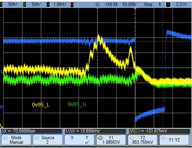
I suspect that the Over-Voltage Protection (OVP) was triggered, causing the Power Good signal to assert low. This behavior is only observed at elevated temperatures (around 70 °C as monitored by the FPGAs). At room temperature, no issues have been reported.

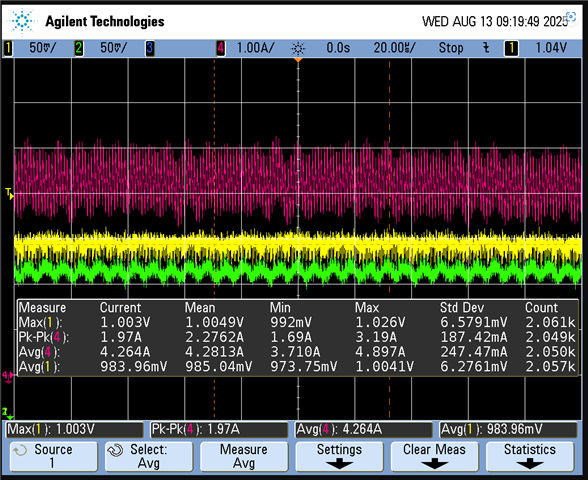
In our application, each rail is delivering approximately 6 A to the loads.


Yellow represents the output voltage of one of the DCDCs, Green represents the output voltage of the other DCDC, and Pink shows the output current of the Yellow DCDC @50C: 


Yellow represents the output voltage of one of the DCDCs, Green represents the output voltage of the other DCDC, and Pink shows the output current of the Yellow DCDC @65C: 


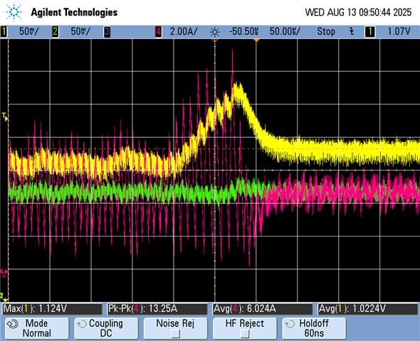
Moment when the power good is active low and DCDC disactivated @65C: 


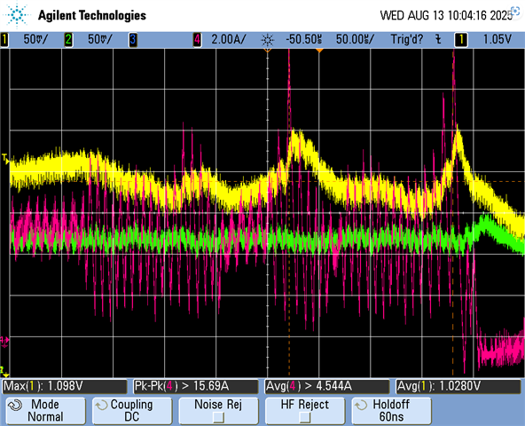
Based on the captured waveforms, the output ripple appears to increase with temperature. Have you encountered this behavior before?

PSpice simulations indicate that the design has a good phase margin, about 60°.

Thanks in advance,
Filipe Costa


  • Hi Filipe,

    Thank you for sharing all the waveforms.  This really helps.  I agree that it does look like the OVP threshold is being reached.  I suspect this is because some component values are changing with temperature.

    How is the temperature being set?  And what temperature is actually being measured?  Ambient, FPGA's junction, PCB temp, etc.?

    Where is the current being measured in your circuit?  Can you share a schematic or part of the schematic?

    The load current is not DC, as it normally is in most lab tests like this.  Is the FPGA running some code that is causing the current to vary like a sine wave?  Are you able to test the system with an external DC load, instead of the actual FPGA load?

    The green and yellow voltage waveforms also show significant ripple or sine waves--at 50mV/div, I would expect these to be much flatter/DC.

    Have you measured a bode plot of your board?  Can you measure it as 25 C and 60 C, for example?  The change in temperature affects capacitor values, for example, and this can impact stability.

    Can you share your PCB layout?  Perhaps something is coupling into the FB pin, which causes the output voltage to rise.

    Finally, this is a very old and large device.  The TPS62872 or TPS6287B15 are much newer, higher performance replacements.  We also have power modules, such as the TPSM8287A12.

    Thanks,

    Chris

  • Hi Chris,

    Thank you for your prompt reply.

    Regarding the temperature tests: initially, we performed all tests at room temperature (25 °C) with no issues observed. Afterwards, we repeated the tests in an oven. For this specific case, the oven temperature was set to 40 °C.

    The monitored temperature is the FPGA die temperature. The FPGA is indeed running code. During the captured waveforms, it is running a functional test in which it transmits and receives video streams. We have not yet tested this without FPGA load.

    Moreover, by design, the green and yellow waveforms should be identical, as the design is the same.
    Unfortunately, we currently do not have the equipment to measure the Bode plot. I have, however, run simulations.

    I’m afraid I cannot share the schematics and layout in a public forum due to confidentiality. Is there another channel through which we could receive support—perhaps via email?

    Regarding your last comment, we understand you might have chosen another part. However, we have used this one in previous projects, and from a procurement standpoint, it is beneficial for us to continue using the LM21212. Nevertheless, I will bring this point to the management team.


    Thanks in advance, 
    Filipe Costa

  • Hi Filipe,

    Sure, you should be able to click on my name (in blue) and then start a 'conversation'.  That is a private channel.  Can you also send the part numbers for the output caps and compensation caps?

    If possible with your system, one quick method to test temperature related items would be to use a hot air gun to heat up different parts of the circuit, such as the LM21212, FPGA, capacitors, etc.  This might then indicate which item is changing with temperature and causing the behavior.

    Simulations are a good start, but we need to have bench measurements of your actual board, with its parasitics, and actual components used and their actual performance at a given temperature.

    Yes, lots of customers re-use previous devices, and this is ok.  We re-design our products every so often to give a better product, just like you are re-designing your product to offer your customers something improved.

    Chris

  • Hi Chris,

    FYI - I have reached out via private message.
    Thank for your support,


    Best regards,
    Filipe Costa

  • Thanks for sharing.  We can keep discussing there.

    Chris

  • Thank you for confirming the solution in the private message.  The IC was not soldered fully/properly to the PCB and was getting too hot.

    Chris