A related question is a question created from another question. When the related question is created, it will be automatically linked to the original question.
If you have a related question, please click the "Ask a related question" button in the top right corner. The newly created question will be automatically linked to this question.
[FAQ] TPS922051: Design considerations to support low output current
TPS922051/0 is a good option to support 4.5-65Vin 1/2A Buck LED driver. In some applications, the input range is wider, the LED current is relative low and there is no other resources to implement analog dimming or flexible dimming. It means that customer can only choose to adjust the Rsense (sense resistor) in order to adjust the LED output current. In this case, what is the key factors to design the circuit?
For example, when VIN=48V, 4-piece WLED and the maximum LED current is 100mA, in general, if following the equation in datasheet (Section 8.2.1.2), the recommend inductance is 1.125mH (choose K=0.2). With the recommended inductance, it will be good to get accurate LED current and good LED current ripple. However, for some customers, this inductance is relative large and will not be good for the total solution size and cost structure. Will it be possible if a typical inductor like 10-100uH is chose and at the same time, good LED current accuracy can still be realized?
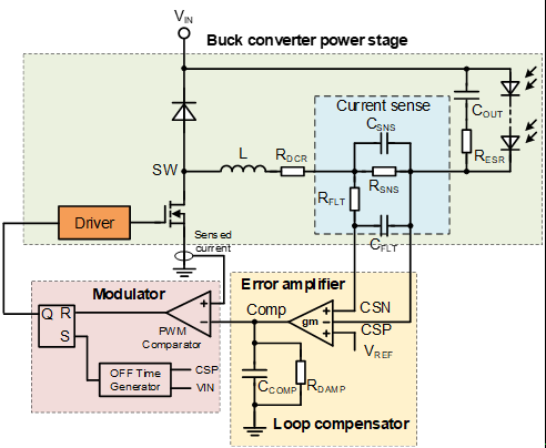
Below figure shows the block diagram of the adaptive off time current mode control Buck LED driver. Just as explained in the datasheet 7.3.1, For average output current regulation, the sensed voltage across the sensing resistor between the CSP and CSN pins is compared with the internal voltage reference, VREF , through the error amplifier. The output of the error amplifier, VCOMP, passes through an external compensation network and is then compared with the peak current feedback at the PWM comparator. During each switching cycle, when the internal NMOS FET is turned on, the peak current is sensed through the internal FET. When the sensed value of peak current reaches VCOMP at the input of PWM comparator, the NMOS FET is turned off and the adaptive off-time counter starts counting. Once the adaptive off-time counter stops counting, the counter is reset until when the NMOS FET stays off. The counting off time is determined by the external resistor connected to the FSET pin and the input/output feedforward. Thus, the device is able to maintain a nearly constant switching frequency at steady state and regulate the output average current at a desired value.
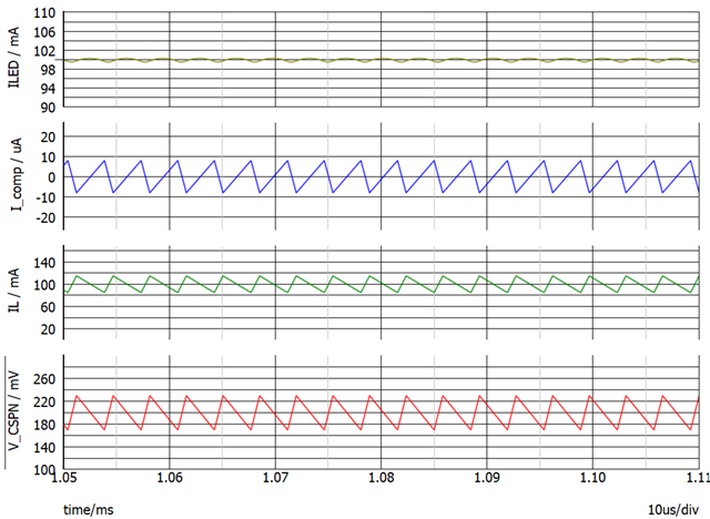
For the error amplifier as shown in the block diagram, it is required that the ac magnitude of the sense feedback CSPN (CSPN=CSP-CSN) should be less than 200mV. Let's take the application case of VIN=48V, 4-piece WLED and 0.1A maximum LED current as an example. Figure 2 shows the waveform of ILED (LED current), IL (Inductor current) and V_CSPN (L=1mH). From the waveform, it shows that the AC magnitude of CSPN is 60mV. In theory, the max value of V_CSPN is Vref*(1+K/2), the min value of V_CSPN is Vref*(1-K/2). K is the ripple ratio of the inductor current (ΔIL / IOUT_MAX). A reasonable value of K is 20% to 60%. The AC magnitude is K*Vref. Thus, when K is selected in the range between 20% - 60%, there is no problem to meet the V_CSPN 200mV ac magnitude requirement.
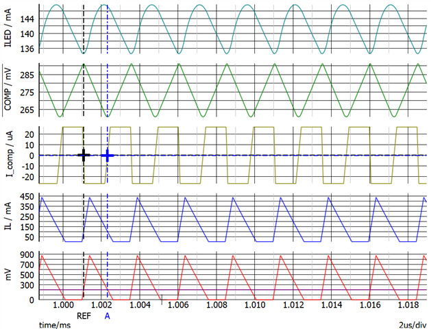
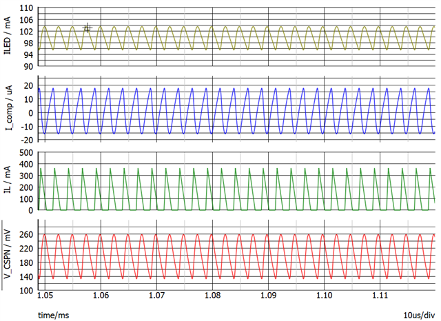
A method is proposed here in order to support lower inductance even with relative low LED current: Adding a sense Csense to suppress the ac magnitude. Figure shows the waveform of ILED, IL, V_CSPN and I_comp (Error amplifier output current) when L=33uH and without Csense. Figure shows the waveform of ILED, IL, V_CSPN and I_comp (Error amplifier output current) when L=33uH and with Csense=1uF. As see from the waveform, without Csense and with typical 33uH inductor, the ILED is 142mA while the target LED current is 100mA which brings a big variation between the measured result and the result in theory. The reason is that the ac amplitude of the sense feedback V_CSPN is large so that the error amplifier is saturated and the output of the EA is clamped. With Csense added, even the inductor is typical as 33uH, the actual LED current can still be accurate as 100mA. Thus, when design the circuit, if power density and good cost structure is required, adding a Csense is good way for low LED current application. Pls measure the voltage across CSPN to make sure that the range of it is within 100mV to 300mV.