LM51772: About each terminal setting

Part Number: LM51772

Tool/software:

Hi All,


I have some questions about LM51772.


(1) When setting the output voltage via I2C, can the FB/SEL_intFB terminal be directly connected to VCC2?
Also, if connected to VCC2, what will the default output voltage be?

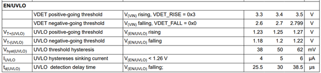
(2) I have a question about the EN/UVLO terminal.
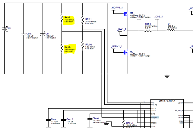
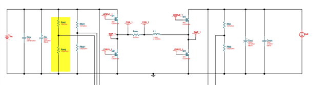
I used webench to refer to the circuit diagram. The EN/UVLO voltage divider resistor values came out to be Rent = 75 kohm / Renb = 348 ohms.
This doesn't seem correct to me. The datasheet says Renb = 12.4 kohm.
If Renb = 348 ohms is correct, please explain why.

WBDesign234.pdf

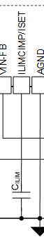
(3) I have a question about the BIAS terminal.
When not in use, I connect it to GND. Is it better to connect it directly? Or would it be better to connect it to GND via a 0.1uF capacitor?


(4) I have a question about the timing of I2C settings.
Is the following understanding of the procedure for setting registers via I2C correct?
1. Input to Vin
2. Set the nRST pin high
3. Set each register via I2C (setting the output voltage, etc.)
4. Set the EN pin high; the set voltage is output from VOUT.
Also, is it possible to change the output voltage or buck-boost operation via I2C while EN is high?


Best Regards,
Ishiwata

  • Hi Ishiwata,

    please see my comments mapped to your questions:

    1, yes, the is the easiest and best way (coinnect FB to VCC2)

    for the LM51772 the default voltage will then be 12V.

    See : SNVSC22 Data sheet | TI.com

    0x258  * 20mV = 600 * 20mV = 12V

    2. There are different approaches used for min voltage to turn on and off and hysteresis

    You can also use the Quickstart calcualor - this allows you more control. Here the min voltages are used to ensure the controller is turned on.

    3. If BIAS is not used connected it to GND directly or just to VIN

    4, yes for the sequence and yes for changing the output voltage during EN high - so you can dynamically change the output voltage. Please also check here the slew rate control which allows to adjust the speed the output voltage changes - important to avoid overcurrent due to too large inrush current.

    Best regards,

     Stefan

  • Hi Stefan,

    Thank you very much for your answer.

    Regarding (2)
    When Renb = 348Ω, it seems that the EN Vth cannot be exceeded and therefore the device will not start. Am I misunderstanding this?

    Regarding (3)
    In Webench, the BIAS pin is connected to GND via a 0.1uF capacitor. Is the 0.1uF unnecessary?


    Best Regards,
    Ishiwata


  • Hi Ishiwata,

    2, this depends on VIN and Rent

    3, I think Webench does not provide the option to not use VBIAS

    Best regards,

     Stefan

  • Hi Stefan,


    Thank you for your answer.

    Please explain (2) again.

    In the Webench circuit diagram below, the input voltage to EN_UVLO is 0.11V when VIN=24V.

    I don't think this reaches the EN threshold voltage, but am I understanding this incorrectly?

    Best Regards,
    Ishiwata

  • Hi Ishiwata,

    it looks like the Webench tool has an issue here.

    I will check with with the Team responsible for Webench but the update might take some time.

    Please use the Quickstart calculator meanwhile. As mentioned it allows much more control on the circuit.

    Best regards,

     Stefan

  • Hi Stefan,

    Thank you for your reply.
    I will tell my customer to refer to the data sheet for (2).

    I have an additional question.


    (5) I have a question about setting the ILIMCOMP/ISET pins.
    For loads such as LEDs, should I refer to equations (23), (24), and (25) for CC-mode or CR-mode on page 42 of the datasheet?
    Or would the calculation results from LM51772_Buck-Boost_Quickstart_Tool_V1_2_0.xlsm be acceptable?

    (6) I have a question about setting the ILIMCOMP/ISET pins.
    The datasheet states that the settings should be as follows.

    LM51772_Buck-Boost_Quickstart_Tool_V1_2_0.xlsm states that the settings should be as follows.

    Which is correct?

    (7) I have a question about setting the overcurrent threshold using ILIM_THRESHOLD via I2C.
    I understand that when setting the ILIM_THRESHOLD register, Rcs = 10mΩ is assumed.
    If the Rcs resistance value is changed, can the ILIMI_THRESHOLD current value be changed accordingly?
    For example, if Rcs = 2mΩ, is my understanding correct? 0x3C = 30mV (3A @ Rcs = 10mΩ) => 15A @ Rcs = 2mΩ).
    If there is a formula for calculating the value when Rcs is changed, please let me know.

    (8) I have a question about setting overcurrent via I2C (MON_LIMITER_EN=Enable).
    Am I correct in understanding that the external ILIMCOMP/ISET constants are disabled?
    Also, assuming setting via I2C, are external constants unnecessary?
    Could you please tell me how to handle the ILIMCOMP/ISET pins in that case?


    Best Regards,
    Ishiwata

  • Hi Ishiwata,

    We have fixed UVLO resistor on WEBENCH, we are getting below combination of resistor for UVLO. These updates will be available on ti.com by next WEBENCH release. tentatively by 26th Aug

  • Hi Ishiwata,

    Checking this with product experts.

    Best regards

    Shaheen

  • Hi Ishiwata,

    5. Please separate ISET = fixed current limit and ILIM = current limit set via DAC

    Best option is to have the footprint for the additional components on the PCB - if you system would require the additional filtering the components could be easily added. For a LED the simple filter should be OK as this does not have a very high dynamic load change.

    6. For ISET it is recommended to have a small cap in parallel to the R to filter out HF noise.  For simplicity this is not shown in the figure in the datasheet.

    7. Yes, this is correct. The R_ISNS is proportional to the current limit.

    Note: R_ISNS is used for the average current limit, not R_CS 

    8. Note sure what you wanted to ask.
    In case you would like to disable the average current limit. Connect ILIMCMP to VCC2 and ISNSP/ISNSN to GND.

    Best regards,

     Stefan 

  • Hi Stefan,


    Thank you for your detailed reply.

    (9) I have an additional question about the EN/UVLO pin.
    Is it possible to control the EN/UVLO pin from another IC by supplying 3.3V or the like via GPIO?
    Also, is it possible to control EN via I2C? If so, how do I handle the EN/UVLO pin?


    Best Regards,
    Ishiwata

  • Hi Ishiwata,

    yes, this is possible.

    The I2C enable and the enable signal from the pin are internally ANDed.
    So only if both have a high state the device will operate.

    Best regards,

     Stefan

  • Hi Stefan,

    Thank you for your support.
    I'll get back to you if I have any additional questions.

    Best Regards,
    Ishiwata


  • Hi Stefan,


    Thank you for your support.

    I have an additional question, so please help me again.

    (9) Regarding the ILIMCOMP/ISET pins
    The circuit I'm considering is planned to be configured via a DAC.
    Would it be better to connect the RC series resistor in the Compensation box in the diagram below to the ILIMCOMP pin?
    In the LM51772 Buck-Boost Quickstart tool V1_2, when configuring via a DAC, only C is shown as directly connected, as shown below. Is this okay?


    (10) Regarding the ISNSP/ISNSN pins
    R_ISNS (the ISNSP/ISNSN pin side) is the average current limiter, and the threshold can be set with RISET or a DAC.
    R_CS (the CSA/CSB pin side) is the inductor current limiter, and the threshold is determined by the Rcs value. I understand that there are two levels of limiting.
    How do these two protections operate, and how are the statuses displayed in the nFLT/Status Byte?
    As I understand it, as shown in the table below, does the overcurrent monitor via R_ISNS only output a monitor voltage to the CDC?

    (11) Regarding the CDC Pin
    I will not be using cable drop compensation. Is it okay to connect the CDC pin to GND?
    If I use the R_ISNS overcurrent protection threshold setting, is it okay to short the CDC pin to GND?

    Best Regards,
    Ishiwata

  • Hi Shuji,

    to your questions:

    9, for a simple filter a C is enough. If a more complex filter, e.g. for better responding to dynamic load, is required an filter like on the COMP pin could be used ( R + C  ||  C).  I recommend to place the footprint for the complex filter, then you can choose the assembly option without layout change.

    10, Fault flag will only be set on OC with sensed with R_CS.    The current limit is seen as normal (wanted) operation mode and not as fault

    ILIM operation can only be checked via I2C  (See: ILIM_OP )

    11, yes, put CDC to GND if not used. Current limit will then still work.

    Best regards,

     Stefan

  • Hi Stefan,


    I apologize for the late reply.
    Thank you very much for your support.

    I have an additional question about R_ISNS.

    (12)
    Does "OC" mean when the average current limit is triggered by R_ISNS?
    Also, referring to the ILIM_OP section on page 57 of the datasheet, it says that the status byte changes when the average current is limited.
    Am I correct in understanding that nFLT also toggles?

    (13)
    Does the inductor current limit by Rcs only function as a hiccup protection,
    and does this mean that the status byte and nFLT pin do not change?

    (14)
    In Table 8-8 (p. 75) of the datasheet, I understand that if any of the status bytes change, the nFLT pin toggles low for 256 μs.
    As for VIN_UV, if the UVLO threshold is set with an external resistor, does that mean the status changes when the voltage falls below that threshold?

    Best Regards,
    Ishiwata

  • Hi Shuji,

    again mapping to your questions:

    12) OC (Over Current) is related to the peak inductor current sensing done with R_CS

           R_SNS is used for current limit

           There for average current limit does not trigger the OC flag  - see also (10) above

    13) Inductor current limit with R_CS can be configured for cycle by cycle or HICCUP mode - see datasheet for details

    14) when configured as nINT it toggles low for 256us. In nFLT it stays low as long as the fault conditions exists.

    Best regards,

     Stefan

  • Hi Stefan,

    Thank you so much for your support.

    Let me confirm.

    Regarding (12)
    I understand that when the average current is limited, the OC flag is not activated, and therefore nFLT does not toggle. Is this correct?

    Regarding (13)
    When the inductor current is limited by R_CS, do the status byte and nFLT pin not change?

    Regarding (14)
    If the UVLO threshold is set by an external resistor, does the status change when the voltage falls below that threshold?


    Best Regards,
    Ishiwata

  • Hi Ishiwata,

    12) correct

    13) not correct: IOUT_OC fault gets set

    14) yes  OFF Flag gets set 

    Best regards,

     Stefan

  • Hi Stefan,

    Thank you so much for your support.


    I would like to use the nFLT/nINT pins from the LM51772 to notify an external microcontroller of changes in the inductor overcurrent (Rcs) and average current overcurrent (Rsns) detection status.
    To clarify the conditions under which the nFLT/nINT flags are raised, I would like to ask another question.

    (15) Am I correct in understanding that no flags are raised for the average current limit on R_SNS?

    (16) I understand that the ILIM_THRESHOLD can be set using R_SNS and the internal DAC, but what is the purpose of setting the threshold?

    (17) I understand that when the average current limit on R_SNS is detected, nFLT/nINT is asserted as shown below. Is this understanding correct?
      Average current limit detected → PD_Status byte (CC_OPERATION in USB_PD_STATUS_0) changes → nFLT/nINT asserts.

    (18) I understand that when an IOUT_OC fault is set, the state of the nFLT/nINT pins changes. Is this understanding correct?

    (19) I understand that if any of the status bytes in Table 8-8 in the datasheet changes, the state of nFLT/nINT will change. Is this understanding correct?


    Best Regards,
    Ishiwata

  • Hi Ishiwata,

    (15) The flag in the USB_PD_STATUS_0 register is set once the average current limit is reached and the device operates in CC mode. There is not fault set but the Interrupt is triggered if enabled

    (16) To have a variable current limit, e.g. for USB-PD the current is negotiated and the power delivery controller is then limiting to that agree max current.

    (17) nINT is triggered but not nFLT (depending on what feature is enabled)

    (18) correct

    (19) correct

    Best regards,

     Stefan

  • Hi Stefan,

    I really appreciate your support.

    Let me double check.

    Please confirm (15) again.
    Am I correct in understanding that the average current limit of R_SNS does not set any flags?


    Please confirm (17) again.
    I have received an answer that whether or not the nINT and nFLT triggers are present depends on whether they are enabled or disabled, but where do I set whether or not the nINT and nFLT triggers are enabled?

     Your answer " nINT is triggered but not nFLT "
    Also, does your answer refer to the default settings?


    Best Regards,
    Ishiwata

  • Hi Ishiwata,

    15): the flag is here: Table 8-7.

    17) please see here:  Table 8-11  -> EN_NINT

    Please check also this section in the datasheet: (this provides details on nFLT and nINT

    SNVSC22 Data sheet | TI.com

    Best regards,

     Stefan

  • Hi Stefan,

    Thank you so much for your support.
    I have a new question to add.


    (20)
    Is there any difference between CONV_EN2 in USB_PD_CONTROL_0 and CONV_EN in the MFR_SPECIFIC_D0 Register?
    Do I need to enable one of them? Or do I need to enable both?

    (21)
    Am I correct in understanding that if SEL_ISET_PIN in MFR_SPECIFIC_D9 is set to DISABLE, the ISET pin will be disabled and the DAC setting will be enabled?


    Best Regards,
    Ishiwata

  • Hi Shuji,

    see the answers mapped to the questions.

    (20) This two bits have the same function and are internally Or'd  - so as soon as one of the two is set to enabled the device will operate

    (21) yes, this is correct

    Best regards,

     Stefan