LMR51450: LMR51450

Part Number: LMR51450

Tool/software:

Hi,

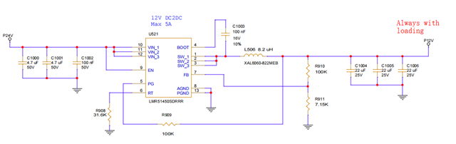
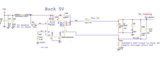
In our board use LMR51450 for 2 application, one is 12V DC2DC output ,another is 5V DC2DC output, both 24V DC input.

12V DC2DC with loading, but 5V DC2DC is reserved function without any loading. We found one strange thing, that the LMR51450 of 5V application has about 3% failure(LMR51450 short, 24V short to ground ), but  LMR51450 of 12V application never have issue


My question is that why LMR51450 broken for 5V DC2DC?

12V DC2DC

5V DC2DC

Best Regards,

Kent

  • Hello,

    Do you have any waveforms for this failure case?

    Also, the input pin of the 5V buck has no input capacitors. The input capacitors must be placed as close to the pin as possible, after the input filter. Also, the input filter has no damping in the form of an electrolytic capacitor. The impedance of the ferrite bead on the input pin as along with the lack of capacitors is likely what is creating a problem for the device. 

    Please refer to the application section of the datasheet for proper placement of the input capacitors.

    Best regards,

    Ridge

  • Hi Ridge,

    Thank you a lot for your quick reply.

    "Do you have any waveforms for this failure case?"

    Sorry we don't have since the chip directly short to ground, so can't capture the waveform.

    If need input cap for chip, may we use 0 RES to replace the ferrite bead for test, check whether circuit more robust ,right?

    Best Regards,

    Kent

  • Hi Kent, 

    Please also send the board layout.

    All buck converters require input capacitance near the IC, as stated in our datasheet recommendation.

    Also, since the input filter is not damped, the Vin may be ringing above the maximum limits to damage the device.

    Replacing the ferrite bead with a 0-ohm may not work. Input capacitors for these devices must be placed as close to the input pin as possible to help filter high frequency noise and stabilize the input.

    For a fast test, you can try the 0-ohm replacement, but if the capacitors are too far away it may not work anyways. Also, those input capacitors must be moved closer. Even a 0-ohm resistance will have parasitic inductance which will degrade the effectiveness of the capacitance for the input of the IC depending on how far away it is from the device pin.

    Please note on the datasheet how close we recommend the input capacitors to be:

    Notice that the HF cap and the larger input capacitors are placed as close to the Vin as possible.

    When you retest, please provide the following waveforms:

    • Vin
    • sw
    • Vout
    • VCC

    Best regards,

    Ridge

  • Closing due to inactivity