


Other Parts Discussed in Thread: TPS7A47
Tool/software:
Hi team,
I want to perform BODE analysis on the following circuit using TINA.
This circuit uses TPS7A47-Q1 as an LDO regulator and connects it in parallel with an NMOS circuit for current expansion.
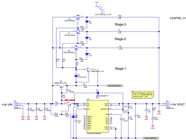
In this circuit, Q6 is suspected to consume a lot of loop margin, so I want to perform a bode analysis. However, the Bode diagram obtained by simulation does not have the cross frequency, as shown below:
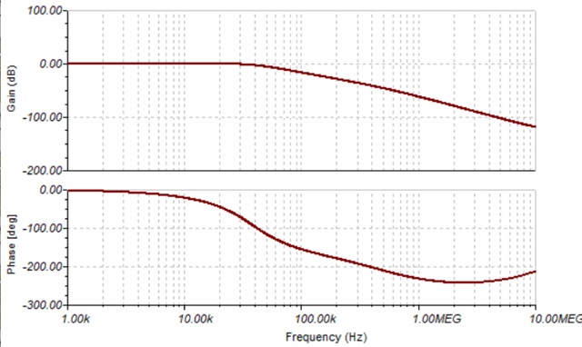
I want to know whether this BODE diagram is normal and how can I analyze it?
See the attachment for the simulation model.
Positive-LDO-Current-sharing_reference.TSC
Thank you for your support!
Best regards!
Ethan