LP8758-E0: [LP8758-E0] Unable to measure current of all BUCKs

Part Number: LP8758-E0

Tool/software:

I have an LP8758-E0 where I'm using all four BUCK and I'm interested in monitoring the current of each output using the internal current measurement. I'm able to get reasonable values when I do the procedure to measure the current on BUCK0 & BUCK1, but BUCK2 & BUCK3 always read 0 where I know there should be a measurement of >20mA. 

My measurement procedure:
1) Write the BUCK source (0-3) into register SEL_I_LOAD (0x21) bits[1:0]
2) Wait the load current measurement time 50us (I wait 100us to be safe)
3) Read registers I_LOAD_2 (0x22) and I_LOAD_1 (0x23) to get the 10bit raw value
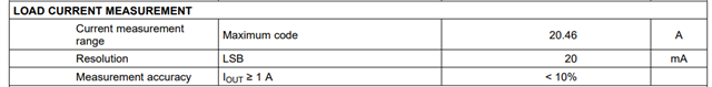
4) Convert to mA by multipling the raw value by 20mA/LSB

This works consistently for BUCK0 & BUCK1, but I always read 0 for both I_LOAD_2 and I_LOAD_1 when performing this for BUCK2 & BUCK3. When I do raw I2C transactions outside of my driver, I get the same results.

What might be going wrong for me?

Thanks,
Rene


  • Hi Rene, 

    Are you using the LP8758-E0EVM, or your own custom board?

    It seems like the command for the buck source into SEL_I_LOAD isn't being written correctly.
    Could this be something with the binary/hex values for 2 and 3?
    Are the correct binary values being written to the register for buck 2 & 3, respectively?

    Can you verify this with some sort of I2C sniffer/logic analyzer on the bus? Or some sort of output log on the driver?

    Best Regards, 
    Sarah

  • Hi Sarah, thanks for looking into this!

    This is on a custom board.

    I can write/read to the device using my RTOS's shell and I can see that the SEL_I_LOAD is correct when I read it back

    All values are in hex, the 60 is the i2c address, 21 is the SEL_I_LOAD

    /* Write value 0x00 to register 0x21 for i2c device at 0x60
    uart:~$ i2c write pmic_i2c_lt@0 60 21 0
    /* Read 3 bytes starting at reigster 0x21 for i2c device at 0x60
    uart:~$ i2c read pmic_i2c_lt@0 60 21 3
    00000000: 00 00 19 |... |

    /* BUCK1 */
    uart:~$ i2c write pmic_i2c_lt@0 60 21 1
    uart:~$ i2c read pmic_i2c_lt@0 60 21 3
    00000000: 01 00 1b |... |

    /* BUCK2*/
    uart:~$ i2c write pmic_i2c_lt@0 60 21 2
    uart:~$ i2c read pmic_i2c_lt@0 60 21 3
    00000000: 02 00 00 |... |

    /*BUCK3 */
    uart:~$ i2c write pmic_i2c_lt@0 60 21 3
    uart:~$ i2c read pmic_i2c_lt@0 60 21 3
    00000000: 03 00 00 |... |


    I've also attached saleae captures of my measurement transactions for BUCK0, BUCK2, BUCK3
    BUCK0
    BUCK2
    BUCK3

  • Hi Rene, 

    Thanks for the info!

    Are you able to check the status of the I_LOAD_READY bit (bit 0 of register 0x18) ?
    I believe you can also monitor the nINT status, and an interrupt will be generated when the load current measurement is ready. 

    After you write the buck# to SEL_I_LOAD, 
    wait until I_LOAD_READY = 1,
    read back I_LOAD_1 & _2 registers

    Best Regards,
    Sarah

  • Hi Sarah, 
    The I_LOAD_READY bit of INT_TOP (register 0x18) is set when I read it and I still read back zeros in I_LOAD_2 and I_LOAD_1

    /* Setup BUCK2 measurement */
    uart:~$ i2c write pmic_i2c_lt@0 60 21 2

    /* Read the INT_TOP register (0x18) */
    uart:~$ i2c read pmic_i2c_lt@0 60 18 1
    00000000: 01 |. |

    /* Read the SEL_I_LOAD, I_LOAD_2, and I_LOAD_1 registers (0x21, 0x22, 0x23) */
    uart:~$ i2c read pmic_i2c_lt@0 60 21 3
    00000000: 02 00 00

    Same with BUCK3:
    uart:~$ i2c write pmic_i2c_lt@0 0x60 0x21 0x3
    uart:~$ i2c read pmic_i2c_lt@0 0x60 0x18 0x1
    00000000: 01 |. |
    uart:~$ i2c read pmic_i2c_lt@0 0x60 0x21 0x3
    00000000: 03 00 00

    EDIT: I should also mention that we are not using any of the interrupt capabilities of the device, if that matters

    Rene

  • Even manually clearing The I_LOAD_READY bit (by writing 1 to that field) before writing to SEL_I_LOAD results it being set again and zeros read back:
    uart:~$ i2c write pmic_i2c_lt@0 60 18 1
    uart:~$ i2c read pmic_i2c_lt@0 60 18 1
    00000000: 00 |. |
    uart:~$ i2c write pmic_i2c_lt@0 60 21 3
    uart:~$ i2c read pmic_i2c_lt@0 60 18 1
    00000000: 01 |. |
    uart:~$ i2c read pmic_i2c_lt@0 60 21 3
    00000000: 03 00 00

  • Hi Rene, 

    Thanks for the update. This is strange, it does look like the commands are being recognized correctly.

    The same loads you tested on Bucks 0 and 1 are also applied on Bucks 2 and 3?
    And do you have multiple boards you are able to test this on, or just the one?

    Best Regards, 
    Sarah

  • Hi Sarah,
    They are different loads and we see the same results across multiple boards. I attached an ELOAD to each of the PMIC outputs and tested various loads:

    All ELOAD and PMIC values are in milliamps.

    BUCK0 0.9v
    ELOAD PMIC
              0        0
          100    180
          200    300
          300    420
          400    540
          500    640
          600    740

    BUCK1 1.5v
    ELOAD PMIC
              0        0
          100      20
          200    140
          300    300
          400    440
          500    560
          600    660

    BUCK2 1.2v
    ELOAD PMIC
              0        0
          100        0
          200    100
          300    240
          400    380
          500    520
          600    620

    BUCK3 1.8v
    ELOAD PMIC
              0        0
          100      20
          200    140
          300    300
          400    440
          500    580
          600    680

    It appears to me that the measurements at the lower ends are not as reliable or linear as I would have thought.

  • Hi Rene, 

    I'm looking through our test data on the current measurement accuracy, and it looks like operating temperature, VIN, and VOUT can all slightly effect the accuracy of the measurement reading.
    Measurements were found to be more accurate at higher temp (~85C) 
    Could you mention what VIN you are using for this system?
    I want to confirm if we are seeing similar results on the EVM. 

    Generally, I'm seeing a similar result, for load currents < 1 A, the accuracy will vary more, 
    but for load currents ≥ 1A, accuracy is improved, and follows the 10% accuracy stated in the datasheet. 

    I apologize that the datasheet wasn't very specific about the accuracy at lower currents.
    And perhaps a minimum current needs to be added to the datasheet, since the reading may not pick up on the actual load being applied at < 200 mA.

    Best Regards,
    Sarah

  • Hi Sarah, 
    Thanks for confirming that on your side, our VIN is 5V.

    Thanks,

    Rene

  • Hi Rene, 
    Thanks for the VIN information, I can confirm that we are seeing similar results for 5V VIN. 

    Best Regards, 
    Sarah