TPS4813-Q1: Available options, replacements

Part Number: TPS4813-Q1
Other Parts Discussed in Thread: BQ76952, TPS4811-Q1

Tool/software:

Hi Team, 

I am looking for a gate driver similar to TPS4813 with Vgs protection and current sensing. One criteria being that the current sensing is similar to that of BQ76952, where in the value of the shunt is written into the gate drivers register, the adc conversion part is taken care by the gate driver and then it sends the current value to the microcontroller. Could you please suggest some gate drivers that meet the requirement ?

Thanks, 

Karthik.

  • Hi Karthik,

    I am working on this and will get back to you soon.

    Thanks,

    Rishika Patel

  • Hi Rishika Patel,

    Sure.

    Thank you,

    Karthik.

  • Hi Karthik,

    The TPS4811-Q1 may be a good fit; it has a current monitoring pin. By VGS protection, are you referring to the V(G1_GOOD)/V(G2_GOOD) thresholds? 

    Are there any other concerns/requirements - reverse polarity, low power mode, etc.?

    Thanks,

    Rishika Patel 

  • Hi Rishika Patel,

    I have the following questions regarding TSP48111.

    1. In the evaluation modeule for TPS48111(https://www.ti.com/lit/ug/sluuck8a/sluuck8a.pdf?ts=1756361597611&ref_url=https%253A%252F%252Fwww.ti.com%252Ftool%252FTPS48111Q1EVM) the gate resistor value on the precharge was 0, 2.21 for the main mosfets. Is there any calculation for the gate resistors ?

    2. Is there any need of gate source resistors for the mosfets ? If yes then how can we get the value of the Rgs ?

    3. Can pin (G) -> pin 11, the prechagre gate driver support 2 mosfets in a common source configuration ? 

    4. The IMON pin has a resistor that can be configured to scale down the current and also the voltage to give it to the microcontroller (0 - 3.3V), so is this a single ended analog signal that is given directly to the microcontrollers analog input ?

    5. Vsns of 30mV, the current sense accuracy is +=2%, is the error percentage constant accross all the load current conditions or dose it change with change in load current ?

    6. The INP_G and INP pins are for controlling G and PU, PD. Is the control over precharge and main mosfets an individual control ? In TPS4813 the over lap time for the mosfets was set and cannot be changed according to our requirement, are there any such limitations in this ic ?

    7. Do short circuit protection and over current protection differ only by their ability to retry, or is there any kind of delay before any of the protection kicks in ?

    Thank you, 

    G Karthik.

  • Hi Rishika Patel,

    I also wanted to ask if there is any charge pump undervoltage protection from the gate driver where in if the charge pump hasnt reached a threshild then the mosfets will not be turned on.

    How reliable is mosfet rdson based current sensing ? Can we replace shunt with Rdson based sensing ?

    Thank you,

    Karthik.

  • Hi Karthik,

    I am working on this, I will get back to you soon.

    Thanks,

    Rishika Patel 

  • Hi Rishika Patel,

    Sure.

    Thank you,

    Karthik.

  • Hi Rishika Patel,

    Also wanted to knowif there is any filtering circuit that is needed on the shunt(Rsns).

    Thank you,

    Karthik.

  • Hi Rishika Patel,

    Also wanted to aks about what is the minimum value for the shunt i can go with to make sure that i have a good current sense accuracy ?

    In all of the diagrams shown (datasheet), eval baord the shunt is on high side, can we have the shunt on low side ? If yes then what configurations should we be changing ?

    Thank you,

    Karthik.

  • Hi Karthik,

    1. No, the gate resistors are there to mitigate line inductance and to dampen high frequency oscillations. They can be increased if needed. 

    2. GS resistors are not required. 100k resistor can be used though. 

    3. Checking on this.

    4. Yes, it is an analog current monitor output.

    5. Checking on this.

    6. Yes, the controls are individual. If you are referring to automatic load wake-up, this device does not have that feature.

    7. Both will eventually either auto-retry or stay latched off depending on how the device is configured. The difference is when the gate goes low after the current fault is reached. Short circuit is fixed time and overcurrent time can be set. 

    8. Yes, there is a charge pump UVLO that will turn off the FETs.

    9. Please see section 9.4 Power Supply Recommendations in the datasheet for RSNS filtering components. 

    10. The TPS4811-Q1 cannot do low-side sensing.

    Thanks,

    Rishika Patel 

  • Hi Rishika Patel,

    Thanks for the support, had a followup question on the UVLO of charge pump. It is not listed a s a fault so when a charge pump UVLO is detected and the FETS are off then will there be any indication given from the gate driver to the microcontroller that the charge pump UVLO is triggered ? The data sheet shows only IMON(analog), FLT_I and FLT_T as output to the microcontroller.

    Thanks, 

    Karthik.

  • Hi Rishika Patel,

    Also wanted to know if there is any filtering circuit that is needed on the shunt(Rsns). The eval board shows a 100 ohm from CS+.

    Thank you,

    Karthik.

  • Hi Karthik,

    3. Yes, the pre-charge path can support 2 back-to-back FETs. 

    5. Yes, since VSNS = I_LOAD × RSNS, the load current does affect VIMON accuracy. Please use the equation below from section 8.3.5 Analog Current Monitor Output (IMON) in the datasheet to calculate V(IMON) accuracy. 

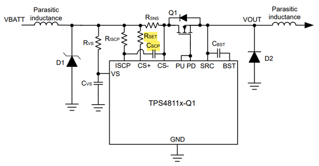
    9. If you have EMI concerns, connect ferrite beads to the CS+ and CS- pins. It is recommended to have a filter capacitor of 1 nF (CSCP) across ISCP and CS- pins close to the device to prevent false short circuit trips. Are you referring to the 100Ω RSET resistor? That is already part of the basic/necessary configuration.

    Please see section 9.4 Power Supply Recommendations in the datasheet. 

    11. BST UVLO will not be reported on the FLT pins. 

    Thanks,

    Rishika Patel