Tool/software:
Hi,
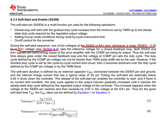
I would like to ask for your clarification regarding the soft-start behavior of the UCC28950.
[Background]
According to equation (1) in the datasheet, the soft-start time Tss can be calculated as:
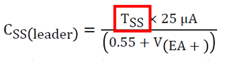
With Css=1 µF, EA+=2.5 V, Iss=25 µA, the calculation results in:
| Parameter | Value | Note |
|---|---|---|
| Css | 1 µF | |
| EA+ | 2.5 V | Vref divider assumed |
| Iss | 25 µA | typ |
| Tss | 122 ms | calculated |
However, actual measurement results show shorter rise times:
-
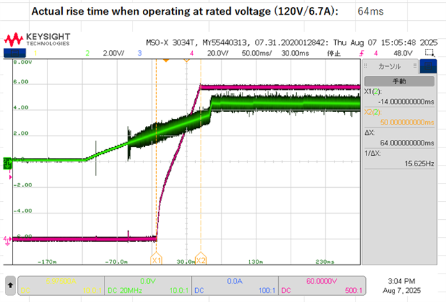
At rated load (120V / 6.7A): Output rise ≈ 64 ms
-
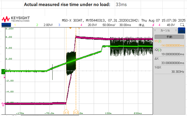
At no load: Output rise ≈ 33 ms
Both are significantly shorter than the calculated Tss (122 ms).
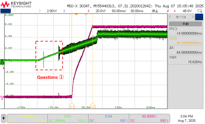
[Questions]
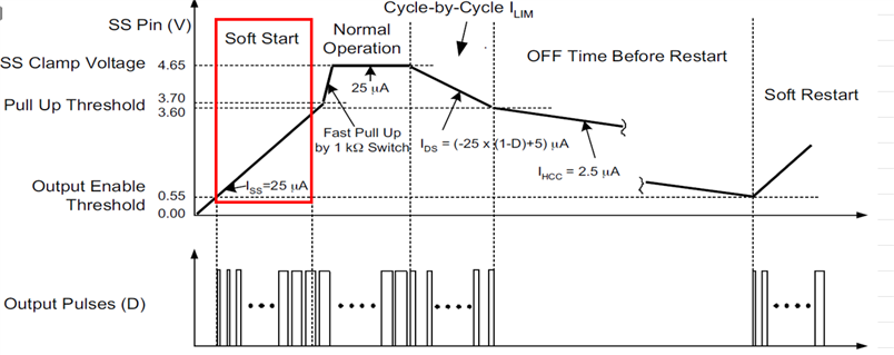
① In Figure 6-15, soft-start is specified to begin at VSS ≥ 0.55 V. However, in measurement, the output only starts rising after VSS exceeds around 1 V.
-
Since VSS is specified up to 0.7 V maximum, could you clarify why this difference occurs?
-
We observe some noise-like behavior around 0.5 V, but actual startup occurs after VSS exceeds ~1 V.

② Tss is defined as the period during which duty cycle gradually increases.
-
Is it correct that the maximum duty is defined by the IC specification (95% typ)?
-
In our measurement, the duty cycle saturates around 50% even at rated load. Is this expected behavior?

③ The measured output rise time is shorter than the calculated Tss, often about half.
-
Our understanding is that the effective rise time is determined when VSS reaches EA+, at which point the output voltage settles to its target, depending on the required duty for the load.
-
Could you confirm if it is correct to interpret that Tss is the time for duty to increase from 0% to 95% (typ), while the actual output rise time depends on the load condition and the duty level at which the output voltage reaches regulation?
Example for Tss=100 ms:
| Load condition | Duty reached | Rise time (calculated) |
|---|---|---|
| No load | 10% | 10.5 ms |
| Rated load | 50% | 52.6 ms |
| Heavy load | 70% | 73.7 ms |
Thus, the output rise time varies with load conditions, and does not always match the calculated Tss. Could you please confirm this understanding?
We would appreciate your feedback on these points.
Best regards,
Conor