Other Parts Discussed in Thread: BQ25731
Tool/software:
I am planning to use this part for An application where in VBUS voltage is 15V
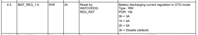
I have the battery of 2s2p 8.4 volt max all the configuration is programmed based on 2s2p with charging current of 2.5A and safe discharging of 5A
now CPU and other loads are connected to a VSYS ,I have a requirement of charging a E-cap to 15V for a LED circuit During 15V charger plug in I am able to use the PMID pin voltage to charge the E-CAP
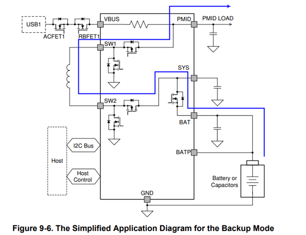
When charger is removed can i boost the battery voltage to 15v and get this in PMID pin ? what is the limitation of the current when USB charger is plugged and during this backup boost mode how to configure and use this mode please help