TPS4816-Q1: TPS48161 Design information missing

Part Number: TPS4816-Q1

Tool/software:

Hi,

I am trying to design with the TPS48161 as the TPS48160 is out of stock everywhere. There seem to be a few errors and omissions in the datasheet that is making the design difficult. There is also no development board reference design to look at. 

1) There is no design procedure for the TPS48161 version, only the TPS48160. The parts are different in how they handle overcurrent situations with only the I2T version presented.

2) Formula (20) will give negative resistances. There appears to be an error. Please advise.

3) The method of selecting Rsetf and Rsetr is not detailed anywhere.

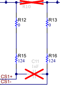
4) On page 37, above Figure 9-13, the paragraph mentions adding "placeholder for RC filter components across the sense resistor and tweak the values during test in the real system". The caption for figure 9-13 indicates the optional components are shown in the figure but the RC filters for Rsense appear to have been left out. Where do they go and what would be typical starting values?

I look forward to hearing from you,

James

  • Hi again,

    I had another follow up question: what type of NTC is the TPS4816 designed for? Obviously any type can be made to work, but the 330/1k Ohm series resistor must have been specified with a particular NTC or specification of NTC in mind. Could you please advise?

    Thanks again,

    James

  • Hi James,

    I am working on this, I will get back to you soon. Sorry for the delay!

    Thanks,

    Rishika Patel 

  • Rishika,

    I am keen to hear from you as my project timeline is starting to stretch due to the delay in getting an answer. If you could please update me on your progress or provide a partial answer it would be very much appreciated. The ticket has been open for a week at this point.

    Regards, 

    James

  • Hi James,

    Sorry for the delay!

    1. The design procedure will be the same unless specified otherwise like for V(IMON); please ignore the I2T calculations for TPS48161-Q1 variant. 

    2. The RISCP equation is correct. If the formula is giving negative resistance values, that means the RSNS resistor has to be modified. 

    3. The recommended range of RSET is 100Ω– 500Ω. RSETF/R are typically the same. 

    4. Please see below; the RSET resistors can act as the resistive component in the RC filter, the following schematic just provides extra placeholders. The following values can be used when starting and modified after testing. Placeholders for ferrite beads can also be added on these pins if EMI is a concern.

    I am still checking on some information with our systems engineer. 

    Thanks,

    Rishika Patel 

  • Rishika,

    Thanks for the update

  • Hi James,

    For RSET, calculate VSNS_MAX = IOC_MAX x RSNS. Then, RSET = VSNS_MAX / ISET (max ISET can be is 1mA). 

    NTC - NCU18WB473J6SRB 

    Thanks,

    Rishika Patel