


Tool/software:
Hi all.
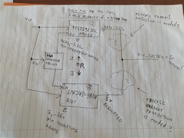
i would like to drive the PCB 5v system voltage as described in the picture attached. two main items from TI will take place in the design.
only one of them will be enabled at a given time.
since the internal MOSFET of each one of them is N-CH, then the Mosfet diode will be open for driving reverse currents, even when each item, in its turn, is not enabled.
the issue here is that both items are connected to the same VIN, so i don't think we need the extra protection for reverse polarity current here (ideal diode). since the VIN must be valid when each one of them will be enabled. otherwise, there is no power to the design. if an ideal diode is to be added here, i think it is better to add it after the BUCK - LM61480-Q1, your comments on that as well???
but i would appreciate TI experts, reviewing the attachment, who are familiar much better than me with these items, check if i am missing something here, and send me your comments on the suggested design???
thx.
nitsan.
