LP8860-Q1: About LP8860 power consumption calculation

Part Number: LP8860-Q1

Tool/software:

HI   Engineer 

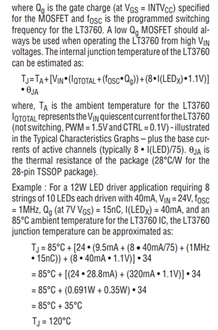
The current plan is to use the LP8860 to drive LED lights, utilizing 4 channels with a maximum current of 120mA per channel. The input voltage has a maximum of 12.6V, a minimum of 11.4V, and a typical value of 12V. The maximum output voltage is 40V.Currently, we need to calculate the power consumption or maximum TJ of the LP8860. I couldn’t find relevant information in the datasheet. Please kindly confirm, engineers.

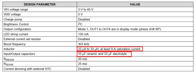
How are the selections of the boost inductor, rectifier diode, output capacitor, and input capacitor calculated? The manual only provides a reference value—is calculation not necessary?

Thank you.

  • Hi, Sheng

    For the power loss of the device, as our device is a controller. The mainly power is from sink, you can calculate as the Vheadroom*Iout*Channel + VDD* Iq. Boost loss is out of the device.

    For the inductor selection and cap selection, you can refer to the application to do the calculation.

  • HI  Wu

    Thank you for your response.

    1. May I ask in which document the formula you mentioned is recorded? I need a corresponding reference. As shown in the figure below, the calculation regarding the junction temperature of the controller chip provided in the LT3760 manual of LT is an example. I require a similar formula.
      I need to evaluate the junction temperature of the controller chip to ensure it meets the operating environmental temperature requirements of our equipment.

    2. Regarding the selection of inductors and capacitors, you mentioned referring to the application note for calculations. However, I have not been able to locate the relevant application note. Could you please provide the document number?

    Thank you.

  • Hi, Sheng

    • For thermal estimation, it is a estimate formula depending on experience. Not mentioned in the datasheet.
    • For the component, application solution can meet most of the case. No specific formula here.

    By the way, we recommend use our new family LP8864/6 to do the design.

  • HI  Wu

    Thank you for your response.

    Regarding the previously mentioned formula [Vheadroom*Iout*Channel + VDD* Iq], what parameter does Vheadroom represent? Please advise.
    Since we are currently using standard components adopted by the company, it is not possible to pursue new alternatives at this time.

    What are the performance parameters of the MOSFET constructed as shown in the figure below? 

    What does VSTA represent as shown in the figure below?

    Thank you.

  • Hi, Sheng

    The saturation current is what we talked about the headroom voltage. During the normal operation, OUT will have the voltage and leads the power dissipation.

  • HI  Wu

    Thank you for your response.

    Is the VSAT mentioned above the saturation voltage of the internal MOSFET in the constant current section of the LP8860-Q1? Can I use this to calculate the power consumption of the internal MOSFET? Voltage * Current.

  • Hi, Sheng

    Sure, you calculated as that.